
Data Sheet
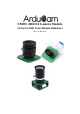

1.2M Pixels CMOS AR0134 CAMERA MODULE
www.ArduCAM.com
4
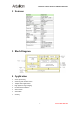
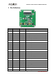
5 Pin Definition
Table 1 HDC1 Connector Pin Definition
Pin No.
PIN NAME
TYPE
DESCRIPTION
1
GND
Ground
Power ground
2
FLASH
Output
Flash output control
3
Trigger
Input
Exposure synchronization input
4
VSYNC
Output
Active High: Frame Valid; indicates active frame
5
HREF
Output
Active High: Line/Data Valid; indicates active pixels
6
DOUT11
Output
Pixel Data Output 11 (MSB)
7
DOUT10
Output
Pixel Data Output 10
8
DOUT9
Output
Pixel Data Output 9
9
DOUT8
Output
Pixel Data Output 8
10
DOUT7
Output
Pixel Data Output 7
11
DOUT6
Output
Pixel Data Output 6
12
DOUT5
Output
Pixel Data Output 5
13
GND
Ground
Power ground
14
DOUT4
Output
Pixel Data Output 4
15
DOUT3
Output
Pixel Data Output 3
16
DOUT2
Output
Pixel Data Output 2
17
DOUT1
Output
Pixel Data Output 1
18
DOUT0
Output
Pixel Data Output 0(LSB)
19
XCLK
Input
Master Clock into Sensor
20
PCLK
Output
Pixel Clock output from sensor
21
SCL
Input
Two-Wire Serial Interface Clock
22
SDATA
Bi-directional
Two-Wire Serial Interface Data I/O
23
RST
Input
Sensor reset signal, active low
24
GND
Ground
Power ground
25
GND
Ground
Power ground
26
STANDBY
Input
Standby-mode enable pin (active HIGH)
27~30
VCC
POWER
3.3v Power supply