Arducam USB3 Camera Shield Data Sheet Rev 1.
Arducam USB3 Camera Shield Data Sheet Table of Contents 1 2 3 4 5 6 7 Introduction ............................................................................................................................. 2 Application............................................................................................................................... 3 Features ....................................................................................................................................
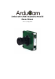
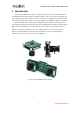
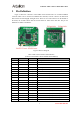
Arducam USB3 Camera Shield Data Sheet 1 Introduction Arducam series USB camera shield is a general purpose USB camera control board for PC and embedded signal board computer. It hides the complex nature of the camera and provides the plug and play camera control interface as well as the ready to use SDK library and demo software source code. The Arducam supports variety camera modules from 0.3MP to 14MP or even higher. Arducam USB3 camera shield is the latest USB3.
Arducam USB3 Camera Shield Data Sheet 2 Application IoT cameras Robot cameras Wildlife cameras Machine vision Scientific cameras 3 Features Support any parallel image sensors (need proper register settings) Support 8/10/12/14/16 bit pixel color depth Support Stereoscopy mode for dual camera system Build-in IRCUT control Need extra MIPI to parallel adapter board for supporting MIPI interface sensors (see Table1) Provide free binary SDK library and demo software source code, please
Arducam USB3 Camera Shield Data Sheet 5 Pin Definition Figure 2 shows the connectors of the USB3 camera shield. There are one Micro-USB3.0 connector which can be connected to USB3.0 host controller, and one connector for motorized IR-Cut filter for both daylight and night vision. There are two camera interface on the bottom of the board, one for 8bit camera data bus and the other for 16bit camera data bus. The pin out definition see Table 2 and Table 3.
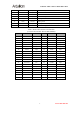
Arducam USB3 Camera Shield Data Sheet 20 PCLK Input Pixel Clock output from Camera 21 SCL Output Two-Wire Serial Interface Clock 22 SDATA Bi-directional 23 RST Output Sensor reset signal, active low 24 GND Ground Power ground 25 GND Ground Power ground 26 STANDBY Output Standby-mode enable pin (active HIGH) 27~30 VCC POWER Two-Wire Serial Interface Data I/O 3.3v Power supply Table 3 16-bit Camera Interface Pin Definition (Connector Part Number: Harwin M50-4302045) Pin No.
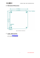
Arducam USB3 Camera Shield Data Sheet 6 Mechanical Dimension Figure 3 Mechanical Dimension 7 Order Information Contact email: admin@arducam.com WhatsApp/Phone: +86 18100618405 6 www.ArduCAM.