
Data Sheet
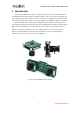

Arducam USB3 Camera Shield Data Sheet
5 Pin Definition
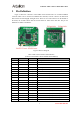
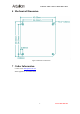
Figure 2 shows the connectors of the USB3 camera shield. There are one Micro-USB3.0
connector which can be connected to USB3.0 host controller, and one connector for motorized
IR-Cut filter for both daylight and night vision. There are two camera interface on the bottom of
the board, one for 8bit camera data bus and the other for 16bit camera data bus. The pin out
definition see Table 2 and Table 3.
Figure 2 Interface Diagram
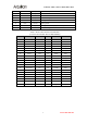
Table 2 8-bit Camera Interface Pin Definition
(Connector Part Number: Hirose FH28D-30S-0.5SH(05))
Pin No. PIN NAME TYPE DESCRIPTION
1 GND Ground Power ground
2 Reserved NC
3 Reserved NC
4 VSYNC Input Active High: Frame Valid; indicates active frame
5 HREF Input
Active High: Line/Data Valid; indicates active pixels
6 DOUT11 Input
Camera Pixel Data Input 11 (MSB)
7 DOUT10 Input
Camera Pixel Data Input 10
8 DOUT9 Input
Camera Pixel Data Input 9
9 DOUT8 Input
Camera Pixel Data Input 8
10 DOUT7 Input
Camera Pixel Data Input 7
11 DOUT6 Input
Camera Pixel Data Input 6
12 DOUT5 Input
Camera Pixel Data Input 5
13 GND Ground Power ground
14 DOUT4 Input
Camera Pixel Data Input 4 (LSB)
15 DOUT3 Input
Camera Pixel Data Input 3 (Unconnected)
16 DOUT2 Input
Camera Pixel Data Input 2 (Unconnected)
17 DOUT1 Input
Camera Pixel Data Input 1 (Unconnected)
18 DOUT0 Input
Camera Pixel Data Input 0 (Unconnected)
19 Reserved NC
www.ArduCAM.com
4