
Data Sheet
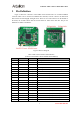

Arducam USB3 Camera Shield Data Sheet
20 PCLK Input Pixel Clock output from Camera
21 SCL Output Two-Wire Serial Interface Clock
22 SDATA Bi-directional
Two-Wire Serial Interface Data I/O
23 RST Output Sensor reset signal, active low
24 GND Ground Power ground
25 GND Ground Power ground
26 STANDBY Output Standby-mode enable pin (active HIGH)
27~30 VCC POWER 3.3v Power supply
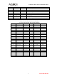
Table 3 16-bit Camera Interface Pin Definition
(Connector Part Number: Harwin M50-4302045)
Pin No. PIN NAME TYPE Pin No. PIN NAME TYPE
1 VCC3.3 POWER 2 VCC3.3 POWER
3 GND Ground 4 GND Ground
5 SDATA Bi-directional
6 SCL Input
7 Data10 Input 8 Data12 Input
9 Data11 Input
10 Data13 Input
11 Data8 Input
12 Data6 Input
13 Data3 Input
14 Data0 Input
15 RST Output 16 Data4 Input
17 Data7 Input 18 Data9 Input
19 Reserved NC 20 STANDBY Output
21 Reserved NC 22 Reserved NC
23 Data14 Input 24 HREF Input
25 Reserved NC 26 VSYNC Input
27 Reserved NC 28 GND Ground
29 PCLK Input 30 GND Ground
31 Data1 Input 32 Data5 Input
33 Reserved NC 34 Data15 Input
35 Data2 Input 36 Reserved NC
37 Reserved NC 38 Reserved NC
39 Reserved NC 40 USB_RST Input
www.ArduCAM.com
5