
Datasheet
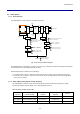
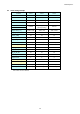
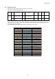
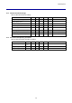
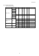
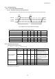
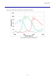
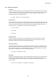
Table Of Contents
- Description
- Features
- Device Structure
- USE RESTRICTION NOTICE
- 1. Block Diagram and Pin Configuration
- 2. Pixel Signal Output Specifications
- 3. Control Registers
- 3-1 2-wire Serial Communication Operation Specifications
- 3-2 2-wire Serial Communication Register Map (Configuration register, Parameter limit register)
- 3-3 Parameter Limit Registers – [0x1000-0x1FFF] (Read Only and Static)
- 3-4 Manufacturer Specific Registers – [0x3000-0x5FFF ]
- 3-5 Frame Bank A and Bank B specific output samples
- 4. Output Data Format
- 6. On Chip Image Processing
- 7. NVM Memory Map
- 8. How to operate IMX219PQH5-C
- 9. Other Functions
- 10. Electrical Characteristics
- 11. Spectral Sensitivity Characteristic
- 12. Image Sensor Characteristics
- 13. Measurement Method for Image Sensor Characteristics
- 14. Spot Pixel Specification
- 15. Notice on White Pixels Specifications
- 16. Chief Ray Angle Characteristics
- 17. Connection Example
- 18. Notes On Handling

IMX219PQH5-C
86
10-4 AC Characteristics
10-4-1 Master Clock Waveform Diagram
10-4-1-1 INCK Square Waveform Input Specifications
Input specifications are shown below when square-wave inputs directly into the external pin INCK.
Fig. 44 Master Clock Square Waveform Diagram
Table 44 Master Clock Square Waveform Input Characteristics
Item
Symbol
Min.
Typ.
Max.
Unit
Comment
Frequency
fSCK
6
18
27
MHz
jitter (period, peak-to-peak)
Tjitter
600
ps
Rise Time
fRISE
1
10
ns
Fall Time
fFALL
1
10
ns
Duty Cycle
fDUTY
40
60
%
Input Leakage
fILEAK
-10
10
µA
10-5 Electrical Characteristics
Table 45 Electrical Characteristics
(V
ANA
= 3.0 V, V
DDL
= 1.3 V, V
DIG
= 1.98 V, Tj = )
Item
Symbol
Min.
Typ.
Max.
Unit
Comment
Current consumption
(Full,30 frame/s)
IVAVA_strm
33
38
mA
VTmax is max speed
read out from pixel array
CSI2 4 lanes, V
ANA
current
IVDDL_strm
100
160
mA
VTmax is max speed
read out from pixel array
CSI2 4 lanes, V
DDL
current
Defect Correction, L.S.C.
function off
HW-Standby current
ISTB_ana
50
µA
XCLR = Lo, V
ANA
current
ISTB_dig
10
µA
XCLR = Lo, V
DIG
current
ISTB_Iddl
50
µA
XCLR = Lo, V
DDL
current
Note) Measurement conditions
tp
0.35VDIG
0.65VDIG
fRIS
E
fFA
LL
0.5VDIG