
12MP IMX477 Mini High Quality Camera Module for Raspberry Pi - Datasheet


IMX477-AACK-C
18
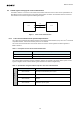
6-3 Clock generation and PLL
IMX477-AACK-C equips embedded PLL to generate the necessary internal clocks and CSI2 transmission clocks. Set
the related registers according to the operation condition. See Software reference manual for more details of each
function.
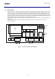
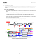
6-3-1 Clock System Diagram
IMX477-AACK-C is equipped with two PLL, One outputs IVTCK for image processing, the other is IOPCK for MIPI
output.
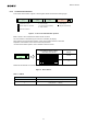
Based on the clock that is input in the range of 6 to 27 MHz, output of 1800 to 2100 MHz can be of the PLL for
IVTCK, PLL of IOPCK for is capable of outputting 1200 to 2100 MHz.
It is possible to divide the range of 1/1 to 1/4 of the PLL IVTCK, and to multiply in the range of 150 to 350.
It is possible to divide the range of 1/1 to 1/4 of the PLL IOPCK, and to multiply in the range of 100 to 350.
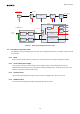
Typically, IMX477-AACK-C can be driven from the dual PLL mode to operate the both of PLLs, but it also supports
single PLL mode to move only one side of the PLL.
In PLL single mode, IOP_PREPLLCK_DIV and IOP_PLL _MPY are ignored.
INCK
EXCK_FREQ
PreDiv_IVT
IVT_PREPLLCK_DIV
PreDiv_IOP
IVT_PREPLLCK_DIV
MPY_IVT
IVT_PLL_MPY
MPY_IOP
IVT_PLL_MPY
Div_CP
[div:2]
Charge
Pump
ADC PipeLine FIFO
MIPI
DPHY
serializer
PLL
ADCK
CPCK
Div_IVT_px
IVT_SYCK_DIV × IVT_PXCK_DIV
Div_IOP_px
IOP_SYCK_DIV × IOP_PXCK_DIV
SEL
1
0
PLL_MULT_DRIV
IOPCK
IVTCK
IVTPXCK
IOPPXCK
Div_IVT_
cont
[div:2]
DIVIDER
CPCK
ADCK(auto setting)
IVTPXCK
IOPPXCK
IOPCK
DCK[P/N]
DMO[1/2/3/4][P/N]
Block diagram
Clock tree
Data Flow
IVTPXCK
Div_AD
HCLK
Figure 10 Clock System Diagram (PLL single mode)