
12MP IMX477 Mini High Quality Camera Module for Raspberry Pi - Datasheet


IMX477-AACK-C
19
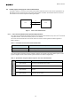
INCK
EXCK_FREQ
PreDiv_IVT
IVT_PREPLLCK_DIV
PreDiv_IOP
IOP_PREPLLCK_DIV
MPY_IVT
IVT_PLL_MPY
MPY_IOP
IOP_PLL_MPY
Div_CP
[div:2]
Charge
Pump
ADC PipeLine FIFO
MIPI
DPHY
serializer
PLL
ADCK
CPCK
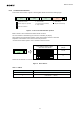
Div_IVT_px
IVT_SYCK_DIV × IVT_PXCK_DIV
Div_IOP_px
IOP_SYCK_DIV × IOP_PXCK_DIV
SEL
1
0
PLL_MULT_DRIV
IOPCK
IVTCK
IVTPXCK
IOPPXCK
HCLK
Div_IVT_
cont
[div:2]
DIVIDER
CPCK
ADCK(auto setting)
IVTPXCK
IOPPXCK
IOPCK
DCK[P/N]
DMO[1/2/3/4][P/N]
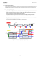
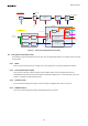
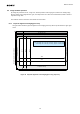
Block diagram
Clock tree
Data Flow
IVTPXCK
Div_AD
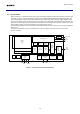
Figure 11 Clock System Diagram (PLL dual mode)
6-4 Description of operation clocks
The following are general descriptions for each clock. See “Clock generation and PLL” of Software reference manual
for more detail.
6-4-1 INCK
INCK is an external input clock (6 to 27 MHz). See “AC characteristics” for electrical requirements to INCK.
6-4-2 IVTCK, IOPCK (PLL output)
These clocks are the root of all the operation clocks in IMX477-AACK-C and it designates the data rate.
DCKP/DCKN; CSI2 interface clock is generated from IOPCK by dividing into 1/2, 1/4 or 1/8 frequency since the
interface is operated in double data rate format.
6-4-3 IVTPXCK Clock
The clock for internal image processing is used as the base of integration time, frame rate, and etc.
6-4-4 IOPPXCK Clock
The clock for internal image processing is designating the pixel rate and etc.