
12MP IMX477 Mini High Quality Camera Module for Raspberry Pi - Datasheet

IMX477-AACK-C
21
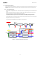
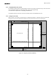
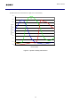
6-5-2 Color coding and order of reading image date
The original color filter arrangement of the sensor is shown in the figure below. Gr and Gb are the G signals shown
at the same line as R signals and B signals, respectively. The line with R & Gr signals and the line with Gb & B
signals are output one after the other alternatively.
Figure 13 Color coding alignment
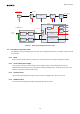
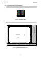
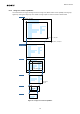
6-6 Output Image Format
This is the output image diagram of full pixel output mode, Image data is output from the upper left corner of the
diagram.
FS
FE
Frame
Blanking
Line
Blanking
4056
3040
Active image area
Long Packet
GR
BG
GR
BG
GR
BG
GR
BG
FRM_LENGTH_LINES
Embedded data lines
2
PF
PH
Gyro data(Size is determined automatically by the system.)
1
Figure 14 Full pixel output mode data structure
Default readout direction
B
Gr
B
Gr
B
Gr
B
Gr
B
Gr
B
Gr
B
Gr
B
Gr
B
Gr
Gb
R
Gb
R
Gb
R
Gb
R
Gb
R
Gb
R
Gb
R
Gb
R
Gb
R