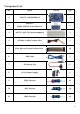
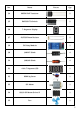
Component List No.
No.
No.
No.
No.
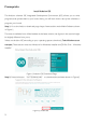
Prerequisite Install Arduino IDE The Arduino software IDE Integrated Development Environment (IDE) allows you to write programs and upload them to your board. Here, you will learn how to set up the software to program your board. Step 1: Go to the Arduino download page: https://www.arduino.cc/en/Main/Software shown in Figure 1. The version available from official website is the latest version, the figures in this tutorial might be slightly different from yours.
Step 3: Double click the "windows.exe" file to the following dialog box and then click "I Agree" and then click "Next". Step 4: Click "Browse" to choose the installation path or enter a directory at the Destination Folder. Click "Install" to initiate installation. Step 5: After installation ended, click "Close" to finish.
Step 6: When the dialog box pop us like Figure 2 shown, Select Always trust software for "Adafruit Industries" and click "Install". Step 7: When the installation is done, click "Close".
Add Libraries and Open Serial Monitor Add Libraries Libraries are a collection of code that makes it easy for you to connect to a sensor, display, module, etc. For example, the built-in LiquidCrystal library makes it easy to talk to character LCD displays. Libraries provide extra functionality for use in sketches, e.g. working with hardware or manipulating data. There are hundreds of additional libraries available on the Internet for download. To use the additional libraries, you will need to install them.
Compile and download program. Click the tools to select the correct board and the port you're using as shown in figure 4 and figure 5. Figure 4 Select Board Figure 5 Select Port Click the verify icon to compile and make sure your program is correct and then click the upload icon to download the program shown in Figure 6 and Figure 7.
communicates by receiving and sending serial data. The serial monitor is the 'tether' between the computer and your UNO. It lets you send and receive text messages, handy for debugging and also controlling the UNO from a keyboard. See the icon on the upper right of Figure 8. You just need to click the serial monitor icon to open it. Figure 8 Serial monitor To send data to the board, enter text and click on the "send" button or press enter.
Lessons Lesson 1 Blink and Breathing LED Overview In this project, you will learn the simplest thing you can do with an Arduino and see physical world by blinking the on-board LED and without doing any programming. Second step, you will learn how to use the PWM square-wave signal to control the external LED as a breathing lamp which gradually becomes brighter and then gradually becomes dark.
to protect the LED. Otherwise, it will burn out! In the following connection schematic, you will see the picture shown "+" "-" + - In the wiring diagram, the longer pin (the curved pin) represents anode, the opposite one is cathode. In the first step experiment we blink the onboard LED by tuning it on and off, the brightness of LED can't be changed. So in the second step we will use PWM technique to adjust the brightness.
Wiring Diagram Result LED is lit up and went out gradually like breathing.
Lesson 2 LED Flowing Lights Overview In this lesson, you will master how to use eight large red LEDs with an UNO or MEGA2560 board without using up 8 output pins. Components required Name Qty Name Qty UNO R3 or MEGA 2560 1 220Ω Resistor 8 LED 8 DuPont Wire 17 74HC595 IC 1 Breadboard 1 Component Introduction The 74HC595 is an 8-stage serial shift register with a storage register and 3-state outputs. Each of which can either be a 1 or a 0.
control the brightness of the LEDs. This pin is active low, so in this lesson we tie it to GND. Connection Schematic UNO R3/ Mega 2560 Digi tal Input/Output Analog Input /RESET SCL 3V3 SDA 5V AREF GND2 GND GND1 D13 VIN D12 D11 A0 D10 A1 D9 A2 D8 A3 A4 D7 A5 D6 D5 D4 D3 D2 D1 D0 220R 74HC595 220R Q7' GND MR Q7 SH_CP Q6 ST_CP Q5 OE Q4 DS Q3 Q0 Q2 VCC Q1 220R 220R 220R 220R 220R ARDUINO-NOHOLE 220R Wiring Diagram Result LEDs flash in turn.
Lesson 3 Digital Inputs-Switches Overview In this lesson, you will master how to use buttons with digital inputs to turn LED on and off. Components Required Name Qty Name Qty UNO R3 or MEGA 2560 1 220Ω Resistor 1 5mm Red LED 1 DuPont Wire 7 Push Switches 2 Breadboard 1 Component Introduction The switch is a simple component. When you press a button or flip a lever, they connect two contacts together so that electricity can flow through them.
Lesson 4 Controlling a RGB LED by PWM Overview In this lesson, you will master how to program the UNO R3 or MEGA 2560 board for RGB LED control and make RGB LED emits a variety of colors. Components Required Name Qty Name Qty UNO R3 or MEGA 2560 1 220 Ω Resistor 3 RGB LED 1 DuPont Wire 4 Breadboard 1 Component Introduction A RGB LED also known as Tri-color LED consists of three LEDs with a red, a green and a blue light. These three colored LEDs are capable of producing any color.
Wiring Diagram Result The RGB LED emit red, green, blue, yellow, white and purple light. Each color will last for 1s then change to another color in turns.
Lesson 5 Active Buzzer Overview In this lesson, you will learn how to generate a sound with an active buzzer. Components Required Name Qty Name Qty UNO R3 or MEGA 2560 Active Buzzer 1 1KΩ Resistor 1 1 NPN Transistor (S8050) Breadboard 1 1 DuPont Wire 10 Component Introduction A buzzer or beeper is a device which can generate audio. An active buzzer will generate a tone using an internal oscillator, so all that is needed is a DC voltage.
Wiring Diagram Result The buzzer will ring for 2s and then mute for 2s.
Lesson 6 Playing Music Overview In this lesson, you will learn how to program the UNO R3 or MEGA 2560 board to control a passive buzzer, and then make the passive buzzer play music. Components Required Name Qty Name UNO R3 or MEGA 2560 1 Passive Buzzer 1 LED 220Ω Resistor 1 Breadboard 1 NPN Transistor (S8050) 1 DuPont Wire 10 1KΩ Resistor Qty 3 3 Component Introduction A passive buzzer requires an AC signal to make a sound.
Wiring Diagram Result The passive buzzer will play music, and the LED blink simultaneously.
Lesson 7 Tilt Ball Switch Overview In this lesson, you will learn how to use a tilt ball switch in order to detect small angle of inclination. Components Required Name Qty Name Qty UNO R3 or MEGA 2560 Tilt Ball Switch 1 DuPont Wire 3 1 220Ω Resistor 1 Component Introduction The tilt sensor is a component that can detect the tilting of an object. However it works like a normal switch but through a different physical mechanism.
Wiring Diagram Result When the sensor tilts to a certain angle, the LED will light up. When the sensor tilts in the opposite direction, the LED will be extinguished.
Lesson 8 7-segment display Overview In this lesson, you will learn how to program the UNO R3 or MEGA 2560 board to control the segment display. Components Required Name Qty Name Qty UNO R3 or MEGA 2560 1 220Ω Resistor 1 7-Segment Display 1 DuPont Wire 9 Breadboard 1 Component Introduction The seven-segment display is a type of electronic display device for displaying decimal numbers compared to the more complex dot matrix displays.
Connection Schematic UNO R3/ Mega 2560 Digi tal Input/Output Analog Input /RESET SCL 3V3 SDA 5V AREF GND2 GND GND1 D13 VIN D12 D11 A0 D10 A1 D9 A2 D8 A3 A4 D7 A5 D6 D5 D4 D3 D2 D1 D0 g f f e + a b a g d b c dp e d + c dp ARDUINO-NOHOLE Wiring Diagram Result The characters "1 2 3 4 5 6 7 8 9" will be shown on the 7-segment display one by one.
Lesson 9 Photoresistor Overview In this lesson, you will learn how to measure light intensity using an Analog Input and use the level of light to control the number of LEDs to be lit up. Components Required Name Qty Name Qty UNO R3 or MEGA 2560 Breadboard 1 LED 8 1 220Ω Resistor 8 74HC595 IC 1 10KΩ Resistor 1 Photoresistor (Photocell) 1 DuPont Wire 19 Component Introduction A photoresistor is a light-controlled variable resistor.
Wiring Diagram Result The stronger light the photoresistor received, the more LEDs will light up.
Lesson 10 Relay Overview In this lesson, you will learn how to control a relay to connect or disconnect a circuit.
Wiring Diagram Result The LED is lit. When a little sound is from the terminal connection, the port COM is connecting to the port NO at the same time. The LED will be turned off after 2s, and then the port COM is connecting to the port NC.
Lesson 11 4-Digit 7-Segment Display Overview In this lesson, you will learn how to use a 4-digit 7-segment display. Components Required Name Qty Name Qty UNO R3 or MEGA 2560 1 4-bit 7-segment Display 1 74HC595 IC 1 220Ω Resistor 4 Breadboard 1 DuPont Wire 17 Component Introduction The four-digit segment display is an 4x8-shaped LED display device composed of 32 LEDs (including four decimal points), these segments respectively named a, b, c, d, e, f, g, h, dig1, dig2, dig3, dig4.
Wiring Diagram Result The character "1 2 3 4 5 6 7 8 9 a b c d e f" shown on 4-bit 7-segment display one by one, the interval is 0.5 seconds.
Lesson 12 Servo Motor Overview In this lesson, you will master how to control a servo motor with the UNO R3 or MEGA 2560 board. Components Required Name Qty Name Qty UNO R3 or MEGA 2560 1 DuPont Wire 3 Servo (SG90) 1 Component Introduction Servo motor is a kind of geared motor that can rotate with a certain angle according to the input pulse's frequency an duty cycle. The input pulse frequency and duty cycle should be in a certain range for proper operation.
Lesson 13 DC Motor Overview In this lesson, you will learn how to control a small DC motor by an UNO R3 or MEGA 2560. Components Required Name Qty Name Qty UNO R3 or MEGA 2560 L9110 1 3-6V Motor 1 1 9V1A Adapter 1 Power Supply Module 1 Fan Blade 1 Breadboard 1 DuPont Wire 9 Component Introduction A DC motor is a kind of transducer that converts direct current electrical power into mechanical power.
Wiring Diagram Result The DC motor rotates in clockwise direction for 1s, and then rotates in counterclockwise for 1s. The action will continue to cycle. And keep on rotating like this way again and again.
Lesson 14 Stepper Motor Overview In this lesson, you will learn how to control a stepper motor. Components Required Name Qty Name Qty UNO R3 or MEGA 2560 1 Stepper Motor 1 1 9V1A Adapter 1 Power Supply Module 1 DuPont Wire 12 Breadboard 1 ULN2003 Stepper Motor Driver Module Component Introduction A stepper motor divides a full rotation into a number of discrete steps. The motor's position can then be commanded to move and hold at one of these steps.
Wiring Diagram Result The stepper motor moves forward 512 steps (rotate a circle) at a high speed and move in the opposite direction at a low speed after 2s. The action will repeat again and again.
Lesson 15 Intrusion Detection by PIR Overview In this lesson, you will learn how to use Passive Infrared (PIR) sensor to detect the movement nearby. Components Required Name Qty Name Qty UNO R3 or MEGA 2560 1 220Ω Resistor 1 PIR Movement Sensor 1 LED 1 DuPont Wire 1 Component Introduction PIR sensors respond to heat and can be triggered by the heat source such as animals as well as people. The output of Passive Infrared (PIR) sensor will go high when the motion has been detected.
Result When someone stands within the sensing range of the module, the LED will light up and delay for a while. When the person exits the sensing range, the LED will turn off after some time delay. In addition, the delay time and detection distance can be adjusted by the resistors on PIR module.
Lesson 16 1602 LCD Display Overview In this lesson, you will learn how to use a character display device 1602 LCD on the UNO and MEGA 2560 board. Components Required Name Qty Name Qty UNO R3 or MEGA2560 1 LCD1602 Module 1 Potentiometer (10k) 1 DuPont Wire 16 Breadboard 1 Component Introduction During the building of your projects for Arduino, you'll often need to read the output data directly from a LCD display.
UNO R3/ Mega 2560 1 2 3 Digi tal Input/Output Analog Input Potenti ometer /RESET SCL 3V3 SDA 5V AREF GND2 GND GND1 D13 VIN D12 D11 A0 D10 A1 D9 A2 D8 A3 A4 D7 A5 D6 D5 D4 D3 D2 D1 D0 LCD1602 K A D7 D6 D5 D4 D3 D2 D1 D0 E RW RS V0 VDD VSS ARDUINO-NOHOLE Wiring Diagram Result The characters "Hello, World" will be shown on the first line of the LCD module, and the second line is the running time (in second).
Lesson 17 Thermometer Overview In this lesson, you will learn how to use LCD display to show the value of current temperature. Components Required Name Qty Name Qty UNO R3 or MEGA 2560 LCD1602 Module 1 10KΩ Resistor 1 1 Potentiometer 1 Thermistor 1 Male to Male DuPont Wire 18 830 Tie-points Breadboard 1 Component Introduction A thermistor is a type of resistor whose resistance varies according to the temperature.
Wiring Diagram Result The current real-time temperature in degrees will be shown on the LCD display as "TEMP XX F". The default unit is Fahrenheit. You can try to replace only two functions to change it to Celsius (functions are in the code annotation).
Lesson 18 Temperature & humidity sensor DHT-11 Overview In this lesson, you will learn how to use a DHT11 Temperature and Humidity Sensor. It's accurate enough for most of projects that need to measure humidity and temperature. Components Required Name Qty Name Qty UNO R3 or MEGA 2560 DHT11 Temp and Humi Module 1 DuPont Wire 20 1 10KΩ Potentiometer 1 Component Introduction The DHT11 Sensor features a temperature & humidity sensor complex with a calibrated digital signal output.
Wiring Diagram Result The real-time humidity will be shown on the first line of the LCD display module as "Humidity: XX.XX%", and the real-time temperature in Celsius will be shown on the second line as "Temp: XX.XX C".
Lesson 19 Joystick Module Overview In this Lesson, you will learn how to use the analog joystick module. Components Required Name Qty Name Qty UNO R3 or MEGA 2560 1 10KΩ Potentiometer 1 LCD1602 1 Joy Stick 1 DuPont Wire 21 Breadboard 1 Component Introduction A joystick is an input device consisting of a stick that pivots on a base and reports its angle or direction to the device under its control.
Wiring Diagram Result There're 3 values “X Y Z” shown on the LCD display module. Push down the joystick, Y will increase accordingly, and vice versa; push the joystick to the right, X will increase, and vice versa. By pressing the joystick, the value of Z will change from 1 to 0. You can use this module in many interesting projects, such as remote control cars.
Lesson 20 Ultrasonic Sensor Module Overview In this lesson, you will learn how to measure the distance by the ultrasonic distance sensor. Components Required Name Qty Name Qty UNO R3 or MEGA2560 1 LCD1602 1 Ultrasonic Sensor Module 1 10KΩ Potentiometer 1 DuPont Wire 20 Component Introduction The HC-SR04 ultrasonic sensor is a device that can measure the distance to an object by using sound waves.
VCC Tr1g Echo Gnd Wiring Diagram Result When the ultrasonic module is aimed at the obstacle, the distance will be displayed on the LCD module.
Lesson 21 IR Remote Controller Overview In this lesson, you will learn how to use an IR receiver to receive the remote controller signal. Components Required Name Qty Name Qty UNO R3 or MEGA 2560 IR Remote Controller 1 IR Receiver Module 1 1 Female to Male DuPont Wire 3 Component Introduction The universal infrared remote controlling system consists of two parts: sending and receiving, the sending part consists of an IR remote controller, the receiving part consists of an infrared receiving tube.
Result Open serial monitor. Then, press the 0-9 key on the remote controller and you’d better to keep the controller pointing at the IR receiver at the same time, then the corresponding number will be shown on the serial monitor like the following picture.
Lesson 22 LED bar graph display Overview In this lesson, you will learn how to control a LED bar graph in a row Components Required Name Qty Name Qty UNO R3 or MEGA 2560 1 10KΩ Potentiometer 1 220Ω Resistor 1 LED Bar Graph 1 Breadboard 1 DuPont Wire 15 Component Introduction The bar graph is made of 10 independent LEDs in a row. Internal schematic diagram for the LED bar graph shows in the right picture.
Result When you turn the potentiometer to the right, The Input voltage of A0 will become larger. You will see that the LEDs are lit from right to left. If you turn the potentiometer to the left, then the LED will turn off from left to right.
Lesson 23 4*4 Matrix Keyboard Overview In this lesson, you will learn how to use the matrix keyboard. Components Required Name Qty Name Qty UNO R3 or MEGA 2560 1 4*4 Matrix Keyboard 1 Male to Male DuPont Wire 8 Component Introduction This 16-button keypad provides a useful human interface for microcontroller projects. The convenient adhesive backing provides a simple way to mount the keypad in varies applications. Schematic of 4x4 matrix keyboard shows in the following picture.
Wiring Diagram Result Open the serial monitor, then press any keys on the 4*4 matrix keyboard, the corresponding key value will be displayed in the serial monitor.
Lesson 24 Real Time Clock Module Overview In this lesson, you will learn how to use the DS3231 Real Time Clock Module. Components Required Name Qty Name Qty UNO R3 or MEGA 2560 1 DS3231 RTC Module 1 DuPont Wire 4 Component Introduction The DS3231 is a low-cost, extremely accurate I2C real-time clock (RTC) with an integrated temperature compensated crystal oscillator (TCXO) and crystal. The device incorporates an onboard battery which maintains accurate timekeeping even when unplugged.
Result Open the serial monitor, the date will refresh every second. You can power off the board and connect again to check if the time remain walking. The RTC module should continue to walk even if it is powered off. COM11(Arduino/Genuino Mega or Mega 2560) Send 61 Long format with month name: Short format witch 12h mode: Today is: Actual month has: Unixtime: 13June 2017 16:29:04 13rd Jun 17, 04:29pm Tuesday, 163 days of the year. 30 days.
Lesson 25 Water Level Detection Sensor Module Overview In this lesson, you will learn how to use a water level detection sensor module. Components Required Name Qty Name Qty UNO R3 or MEGA 2560 1 DuPont Wire 3 Water Lever Detection Sensor Module 1 Component Introduction The water sensor water level module can perceive water by measuring the volume of droplets water through a series of parallel lines exposed traces in order to determine the water level.
Result Open the serial monitor. Insert the water lever detection sensor module into water, you will see that the data displayed in the serial monitor, which represent the depth of the module immersed in water. (Unit: 1/10 mm) Note: Don't immerse the module in water too deep to avoid short circuits.
Lesson 26 Sound Sensor Module Overview In this lesson, you will learn how to use a sound sensor module. Components Required Name Qty Name Qty UNO R3 or MEGA 2560 1 Female to Male DuPont Wire 4 Sound Sensor Module 1 Component Introduction Sound Sensor can detect the sound strength of the environment. The main component of the module is a simple microphone.
Result Open serial monitor. Speak to the microphone on the sound sensor module, the value of the volume will be displayed in the serial monitor.
Lesson 27 MAX7219 LED Dot Matrix Module Overview In this lesson, you will learn how to control an 8x8 dot-matrix display to implement the display of graphical characters or digits you want. Components Required Name Qty Name Qty UNO R3 or MEGA 2560 1 DuPont Wire 5 Max7219 Module 1 Component Introduction This is an 8x8 LED matrix module which serially driven by the MAX7219 common-cathode display drivers.
Lesson 28 Frequency Meter Overview In this lesson, you will learn to build a simple frequency meter with UNO R3 or MEGA 2560. The frequency of square wave is generated by 555 timer, and then it will be sent to the Arduino GPIO pin, the result to serial monitor through USB port.
Wiring Diagram Result Open the serial monitor, the value of square wave frequency, time of high level and low level will be displayed. Turning the potentiometer, the value of frequency will be changed accordingly.
Lesson 29 MPU-6050 Module Overview In this lesson, you will learn how to use MPU6050 module (Inertia Measurement Unit) Components Required Name Qty Name Qty UNO R3 or MEGA 2560 1 MPU6050 Module 1 DuPont Wire 4 Component Introduction The MPU-6050 sensor contains a 3-axis MEMS accelerometer and a 3-axis MEMS gyro in a single chip. The 3 axis are represent the X,Y,Z direction each, so it can sense both velocity of acceleration and rotation in all direction.
Result Open the serial monitor. The value of the acceleration and angular velocity of the X-axis, Yaxis and Z- axis as well as the real-time temperature will be displayed. Turning the MPU6050 module, the values will be changed accordingly. COM11(Arduino/Genuino Mega or Mega 2560) Send AcX = -7456 I AcX = -7976 I AcX = -7576 I AcX = -7944 I AcX = -5824 I AcX = -7388 I AcX = -7880 I AcX = -6704 I AcX = -7736 I AcX = -8008 I AcX = -7656 I AcX = -7696 I AcY = 12012 I AcZ = 5976 I Tmp = 34.
Lesson 30 Controlling Stepper Motor with Remote Overview In this lesson, you will learn a fun and easy way to control a stepper motor from a distance using an IR remote control.
Lesson 31 Controlling Stepper Motor with Rotary Encoder Overview In this lesson, you will learn how to control stepper motors using a rotary encoder.
Lesson 32 ESP8266 Overview The ESP-01S ESP8266 WiFi Module is a self-contained SOC with integrated TCP/IP protocol stack that can let any microcontroller access to your WiFi network. The ESP-01S ESP8266 module comes with pre-programmed AT command set firmware which means that you can simply hook it up to your Arduino directly. In this lesson, you will learn how to use ESP8266 to build a WIFI remote control system.
Connection Schematic Mega 2560 1 2 3 Potenti ometer Digi tal Input/Output Analog Input /RESET SCL 3V3 SDA 5V AREF GND2 GND GND1 D13 VIN D12 D11 A0 D10 A1 D9 A2 D8 A3 A4 D7 A5 D6 D5 A8 D4 A9 D3 A10 D2 A11 D1 A12 D0 A13 A14 TX3 A15 RX3 TX2 RX2 TX1 RX1 SDA SCL LCD1602 K A D7 D6 D5 D4 D3 D2 D1 D0 E RW RS V0 VDD VSS Relay VCC GND IN TX GND EN IO2 RST IO0 3V3 RX ESP 8266 Wiring Diagram 75
Result Click the IP box and enter the IP address (got from Step2) + “:8089", like "192.168.2.200:8089" (Input without quote). Then click the button CONNECT, it will become yellow and show the character CONNECTED. The status of connection will also be shown in the serial monitor. That means the app has communicated with UNO or MEGA2560 through ESP8266 on-board WiFi successfully.
COM11(Arduino/Genuino Mega or Mega 2560) AT+RST Module is ready reboot wifi is OK APIP:”192.168.4.1” STAIP:”192.168.2.200” Server is set up Connected Send OK Next, click button ON, the relay will be switched on, that means the port COM is connected to the port NO. Click the button OFF, the relay will close, that means the port COM is connected to the port NC. The status of the relay will also be shown in the serial monitor.
Lesson 33 Building a Smart Home System Overview In this lesson, you will learn to build a smart home system with ESP8266 and sensors. You can also use the same idea to develop other interesting projects.
Wiring Diagram 79
Result Open the code from lesson 33 and change the SSID and the PASSWORD to match your home WIFI network. Then connect the app to Arduino board using the same steps from the lesson 32. After successful connection, the RTC time will be displayed on the first line of the 1602 LCD. The value of current humility and temperature will be displayed on the second line. The value will also be shown in app after a while.
The MODE button is used to switch between manual mode or automatic mode. The mode will be displayed on the 1602 LCD for 1s when switching. It will be shown in the serial motor as well. COM11(Arduino/Genuino Mega or Mega 2560) AT+RST Module is ready reboot wifi is OK +CIFSR:STATP,”192.168.2.200”+CIFSR:STAMAC,”5c:cf:7f:8f:20:3b”OK Server is set up In automatic mode, if the temperature is higher than the value of Temp_maxlimit, the motor and fan will start working.