
Data Sheet

30
8161D–AVR–10/09
ATmega48PA/88PA/168PA/328P
Notes: 1. These options should only be used when not operating close to the maximum frequency of the
device, and only if frequency stability at start-up is not important for the application. These
options are not suitable for crystals.
2. These options are intended for use with ceramic resonators and will ensure frequency stability
at start-up. They can also be used with crystals when not operating close to the maximum fre-
quency of the device, and if frequency stability at start-up is not important for the application.
8.4 Full Swing Crystal Oscillator
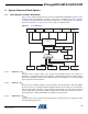
Pins XTAL1 and XTAL2 are input and output, respectively, of an inverting amplifier which can be
configured for use as an On-chip Oscillator, as shown in Figure 8-2 on page 29. Either a quartz
crystal or a ceramic resonator may be used.
This Crystal Oscillator is a full swing oscillator, with rail-to-rail swing on the XTAL2 output. This is
useful for driving other clock inputs and in noisy environments. The current consumption is
higher than the ”Low Power Crystal Oscillator” on page 28. Note that the Full Swing Crystal
Oscillator will only operate for V
CC
= 2.7 - 5.5 volts.
C1 and C2 should always be equal for both crystals and resonators. The optimal value of the
capacitors depends on the crystal or resonator in use, the amount of stray capacitance, and the
electromagnetic noise of the environment. Some initial guidelines for choosing capacitors for
use with crystals are given in Table 8-6 on page 31. For ceramic resonators, the capacitor val-
ues given by the manufacturer should be used.
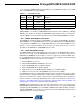
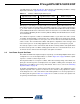
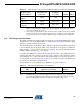
The operating mode is selected by the fuses CKSEL3..1 as shown in Table 8-5.
Notes: 1. If 8 MHz frequency exceeds the specification of the device (depends on V
CC
), the CKDIV8
Fuse can be programmed in order to divide the internal frequency by 8. It must be ensured
that the resulting divided clock meets the frequency specification of the device.
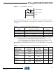
Crystal Oscillator, BOD
enabled
16K CK 14CK 1 01
Crystal Oscillator, fast
rising power
16K CK 14CK + 4.1 ms 1 10
Crystal Oscillator, slowly
rising power
16K CK 14CK + 65 ms 1 11
Table 8-4. Start-up Times for the Low Power Crystal Oscillator Clock Selection (Continued)
Oscillator Source /
Power Conditions
Start-up Time from
Power-down and
Power-save
Additional Delay
from Reset
(V
CC
= 5.0V) CKSEL0 SUT1..0
Table 8-5. Full Swing Crystal Oscillator operating modes
Frequency Range
(1)
(MHz)
Recommended Range for
Capacitors C1 and C2 (pF) CKSEL3..1
0.4 - 20 12 - 22 011