
Product Data Sheet

Arduino MKR WAN 1310
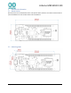
4 Connector Pinouts
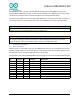
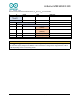
4.1 USB
Note that the board can support USB host mode only if powered via the V
USB
pin and if the jumper close
to the VUSB pin is shorted.
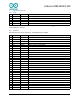
4.2 Headers
Board exposes two 28 pin connectors assembled with pin headers.
Pin
Function
Type
Description
1
V
USB
Power
Power Supply Input. Output is board is powered via V
USB
from header
2
D-
Differential
USB differential data -
3
D+
Differential
USB differential data +
4
ID
Analog
Selects Host/Device functionality
5
GND
Power
Supply Ground
Pin
Function
Type
Description
1
AREF
Analog
Analog Reference.
2
A0/DAC0
Analog
ADC in/DAC out, Can be used as GPIO
3
A1
Analog
ADC in, Can be used as GPIO
4
A2
Analog
ADC in, Can be used as GPIO
5
A3
Analog
ADC in, Can be used as GPIO
6
A4/SDA
Analog
ADC in, I
2
C SDA, Can be used as GPIO
7
A5/SCL
Analog
ADC in, I
2
C SCL, Can be used as GPIO
8
A6
Analog
ADC in, Can be used as GPIO
9
D0
Digital
GPIO, can be used as PWM
10
D1
GPIO, can be used as PWM
11
D2/PWM
Digital
GPIO, can be used as PWM
12
D3/PWM
Digital
GPIO, can be used as PWM
13
D4/PWM
Digital
GPIO, can be used as PWM
14
D5/PWM
Digital
GPIO, can be used as PWM
15
D6
Digital
GPIO, can be used as PWM
16
D7
Digital
GPIO can be used as PWM
17
D8/MOSI
Digital
SPI MOSI, can be used as GPIO, can be used as PWM
18
D9/SCK
Digital
SPI SCK, can be used as GPIO, can be used as PWM
19
D10/MISO
Digital
SPI MISO, can be used as GPIO
20
D11/SDA
Digital
I2C SDA, can be used as GPIO
21
D12/SCL
Digital
I2C SCL, can be used as GPIO
22
D13/RX
Digital
USART RX, can be used as GPIO
23
D14/TX
Digital
USART TX, can be used as GPIO
24
RESETN
Digital
Reset input
25
GND
Power
Power Ground
26
+3V3
Power Out
27
VIN
Power In
Vin Power input
28
+5V
Power Out
Power Ground
8 / 15
Arduino MKR WAN 1310 - 12/23/2020