Arduino® Portenta Breakout Board Product Reference Manual SKU: ASX00031 Description The Arduino® Portenta Breakout board is designed to assist developers with their prototypes by exposing the high-density connectors of the Portenta family on both sides of the breakout carrier, providing total flexibility for measuring and controlling signals - developing your own hardware, testing the design and measuring the input and output signals out of the high-density connectors.
Arduino® Portenta Breakout Board Features Power ON Button Boot mode DIP switch Connectors USBA RJ45 Ethernet up to 1Gb/s; speed depending on installed board Micro SD card OpenMV shutter module MIPI 20T JTAG with trace capability Power CR2032 RTC Lithium Battery backup External power terminal block I/O Break out all Portenta High Density connector signals (see pinout table below) Male/female HD connectors allow interposing breakout between Portenta and shield to debug signals Compatibility Standard Portenta
Arduino® Portenta Breakout Board Contents 1 The Board 5 1.1 Application Examples 5 1.2 Accessories 5 1.3 Related Products 5 1.4 Solution Overview 5 2 Ratings 6 2.1 Absolute Maximum Ratings 6 2.2 Recommended Operating Conditions 7 3 Functional Overview 7 3.1 Board topology 7 3.2 DIP Switch 9 4 Board Operation 9 4.1 Getting started - IDE 9 4.2 Getting started - Arduino Web Editor 9 4.3 Getting started - Arduino IoT Cloud 9 4.4 Sample Sketches 10 4.5 Online Resources 10 4.
Arduino® Portenta Breakout Board 7 Certifications 17 7.1 Declaration of Conformity CE DoC (EU) 17 7.2 Declaration of Conformity to EU RoHS & REACH 211 01/19/2021 18 7.3 Conflict Minerals Declaration 18 8 Company Information 19 9 Reference Documentation 19 10 Revision History 19 4 / 19 Arduino® Portenta Breakout Board / Rev.
Arduino® Portenta Breakout Board 1 The Board 1.1 Application Examples This product is designed to work alongside the Portenta family. Please check the Getting Started guide of your Portenta board. Product Development: The Portenta Breakout board reduces development time for industrial grade solution automation based on the Portenta line.
Arduino® Portenta Breakout Board Example of a typical installation for a solution including Portenta H7 and Global Shutter Camera Module. A Portenta board must be connected for operation of the Portenta Breakout Board. Example of a typical installation for a solution including Portenta H7 and Global Shutter Camera Module. A Portenta board must be connected for operation of the Portenta Breakout Board. 2 Ratings 2.
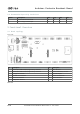
Arduino® Portenta Breakout Board 2.2 Recommended Operating Conditions Symbol Description Min Typ Max Unit T Conservative thermal limits -15 20 60 °C 5V Input voltage from 5V input 4.8 5 5.2 V 3 Functional Overview 3.1 Board topology Front view Ref. Description Ref. Description J1 DF40HC(3.5)-80DS-0.4V(51) High Density connector J5 Micro SD card J2 DF40HC(3.5)-80DS-0.
Arduino® Portenta Breakout Board Ref. Description Ref. Description J15 DF40C-80DP-0.4V(51) High Density connector J16 DF40C-80DP-0.4V(51) High Density connector Shared pins table Some nets/pins are electrically shared in the board and precaution must be taken to avoid conflicts. The full list is presented below.
Arduino® Portenta Breakout Board 3.2 DIP Switch The DIP switch allows for boot mode configuration: BOOT SEL: When set to ON, keeps the Portenta in Boot mode. BOOT: When set to ON enables the embedded bootloader. Firmware can be uploaded via the USB port on the breakout board (DFU). USB-A to USB-A (non-crossover) cable required. The Portenta H7 has to be powered through the USB-C connector or VIN. 4 Board Operation Note: This board is intended to operate together with Portenta H7 (see section 1.
Arduino® Portenta Breakout Board 4.4 Sample Sketches Sample sketches can be found either in the “Examples” menu in the Arduino IDE or in the “Documentation” section of the Arduino Pro website [4] 4.
Arduino® Portenta Breakout Board alt_text In cases where multiple channels are on a single header, the first channel is on the bottom part of the header and the section channel is on the top part of the header. The order of the channel is determined by the silkscreen markings. 11 / 19 Arduino® Portenta Breakout Board / Rev.
Arduino® Portenta Breakout Board 5.1 GPIO Pin Function Type Description 1 3V3 Power +3.3V power rail 2 GPIO 0 Digital GPIO 0 3 GPIO 1 Digital GPIO 1 4 GPIO 2 Digital GPIO 2 5 GPIO 3 Digital GPIO 3 6 GPIO 4 Digital GPIO 4 7 GPIO 5 Digital GPIO 5 8 GPIO 6 Digital GPIO 6 9 GND Power Ground 10 GND Power Ground 5.2 I2C Pin Function Type Description 1 3V3 Power +3.
Arduino® Portenta Breakout Board 5.3 CAN0/CAN1 Pins closer to the edge of the board are CAN0. Pins close to the centre are CAN1. Please Note When used with Arduino Portenta H7, only CAN1 is available. Pin Function Type Description 1 5V Power +5.0V power rail 2 TX Differential CAN Bus Transmission Line 3 RX Differential CAN Bus Receive Line 4 GND Power Ground 5.
Arduino® Portenta Breakout Board 5.
Arduino® Portenta Breakout Board 5.
Arduino® Portenta Breakout Board 5.11 CAMERA: DCMI/CSI Pin Function Type Description 1 GND Power Ground 2 HS Digital DCMI HSYNC 3 CKN Digita DCMI_CLK / CSI CKN 4 CKP Digital DCMI VSYNC / CSI CKP 5 D3N Digital DCMI D6 / CSI D3P 6 D3P Digital DCMI D7 / CSI D3P 7 D2N Digital DCMI D4 / CSI D2N 8 D2P Digital DCMI D5 / CSI D2P 9 D1N Digital DCMI D2 / CSI D1N 10 D1P Digital DCMI D3 / CSI D1P 11 D0N Digital DCMI D0 / CSI D0N 12 D0P Digital DCMI D1 / CSI D0P 5.
Arduino® Portenta Breakout Board 6 Mechanical Information 6.1 Board Outline alt_text 7 Certifications 7.1 Declaration of Conformity CE DoC (EU) We declare under our sole responsibility that the products above are in conformity with the essential requirements of the following EU Directives and therefore qualify for free movement within markets comprising the European Union (EU) and European Economic Area (EEA). 17 / 19 Arduino® Portenta Breakout Board / Rev.
Arduino® Portenta Breakout Board 7.2 Declaration of Conformity to EU RoHS & REACH 211 01/19/2021 Arduino boards are in compliance with RoHS 2 Directive 2011/65/EU of the European Parliament and RoHS 3 Directive 2015/863/EU of the Council of 4 June 2015 on the restriction of the use of certain hazardous substances in electrical and electronic equipment.
Arduino® Portenta Breakout Board 8 Company Information Company name Arduino S.r.l. Company Address Via Ferruccio Pelli 14, 6900 Lugano, TI (Ticino), Switzerland 9 Reference Documentation Ref Link Arduino IDE (Desktop) https://www.arduino.cc/en/Main/Software Arduino IDE (Cloud) https://create.arduino.cc/editor Cloud IDE Getting Started https://create.arduino.cc/projecthub/Arduino_Genuino/getting-started-with-arduinoweb-editor-4b3e4a Arduino Pro Website https://www.arduino.