
User`s manual

Installation Guide
11
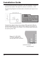
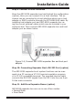
Step 3. Mounting ARC-8026 Expander Box into the Enclosure
Remove the enclosure cover and nd a 5.25 inch CD-ROM wide
place to fasten the ARC-8026 expander box in the external enclo-
sure. The expander box requires one 5.25” half-height drive bay.
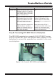
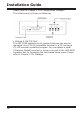
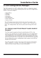
Step 4. Connecting Expander Controller Power
The ARC-8026 series expander box supports 6 pin PCI-E power
connector from PCB version 1.0. If your power supply doesn’t have
a 6 pin PCI-E power cable then you can use the adapter to convert
two 4 pin peripheral power cables into a PCI-E power cable. If you
use an adapter then be sure to plug the 4 pin peripheral power
connectors into separate power cables coming from the power sup-
ply.
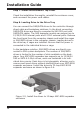
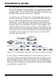
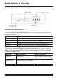
Step 5. Install the LED Cable (option)
Please check the method which controls fault LED on the back-
plane. If the backplane supports SGPIO feature, ignore the indi-
vidual fault LED cable connection. The preferred I/O connector for
server backplanes is the Min SAS 4i (SFF-8087) internal connec-
tor. This connector has eight signal pins to support four SAS/SATA
drives and six pins for the SGPIO (Serial General Purpose Input/
Output) side-band signals. The SGPIO bus is used for efcient
fault/activity LED management and for sensing drive locate status.
See SFF 8485 for the specication of the SGPIO bus. For backplane
without SGPIO supporting, Please refer to section step 5-1. LED
cables for fault/activity LED cable installation.
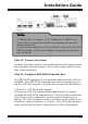
Step 5-1. Install and Re-check Fault LED Cable Connections
(option)
Make sure that the proper failed drive channel information is dis-
played by the fault LEDs. An improper fault LED cable connection
will tell the user to ‘‘Hot Swap’’ the wrong drive. This can result in
removing the wrong disk (one that is functioning properly) from
the controller. This can result in failure and loss of system data.