SurroundVideo® Omni INSTALLATION MANUAL AV12176DN-NL AV12176DN-28 AV12176DN-08 AV20175DN-NL AV20175DN-28 AV20175DN-08
SurroundVideo® Omni Arecont Vision SurroundVideo® Omni Installation Manual SurroundVideo® Omni Installation Contents Package Contents....................................................................................................................................................... 3 Warranty Information ................................................................................................................................................ 4 Installation Overview ................................
SurroundVideo® Omni Arecont Vision SurroundVideo® Omni Installation Manual Package Contents Item MegaPixel Camera Mounting Kit Power Cable I/O Cable Arecont Vision CD Description SurroundVideo® Omni Ceiling template 3x Mounting Screws (#6x1” for wood or sheet metal) 3x Drywall/Masonry Mounting Anchors Ceiling Gasket Network Patch Cable Security Torx Tool Adapter plate (for drop ceiling) 3x Mounting Screws ((#6x2” for adapter plate) Aux Power Cord Digital Input and Output Adapter Manual, Warranty, Instal
SurroundVideo® Omni Arecont Vision SurroundVideo® Omni Installation Manual Warranty Information 3 Year Limited Warranty ARECONT VISION warrants to Purchaser (and only Purchaser) (the “Limited Warranty”), that: (a) each Product shall be free from material defects in material and workmanship for a period of thirty-six (36) months from the date of shipment (the “Warranty Period”); (b) during the Warranty Period, the Products will materially conform with the specification in the applicable documentation; (c)
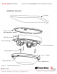
SurroundVideo® Omni Arecont Vision SurroundVideo® Omni Installation Manual Installation Overview Ceiling Gasket (Not required for indoor) NPT Port ( Camera Housing Camera Gimbals (4X) Mounting Screws Gasket Captive Fasteners Page | 5 support@arecontvision.
SurroundVideo® Omni Arecont Vision SurroundVideo® Omni Installation Manual Installation Overview (with Adapter Plate) Tethering Eyelet (Bend by hand) ( Adapter Plate* Drop Ceiling Gasket (Not required for indoor) NPT Port ( Camera Housing Camera Gimbals (4X) Mounting Screws Gasket Captive Fasteners Page | 6 support@arecontvision.
SurroundVideo® Omni Arecont Vision SurroundVideo® Omni Installation Manual Camera Setup The SurroundVideo® Omni is user configurable. Each individual sensor can be positioned in a variety of ways. Below are some example configurations (top left to bottom right) 1. 270° 2. Straight Line 3. 360° or Hallway 4. 180° or Panoramic 5. Random Example 6. Random Example. Tech Tip Page | 7 Prior to installing the camera, thought should be given to the sensor positions.
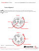
SurroundVideo® Omni Arecont Vision SurroundVideo® Omni Installation Manual Camera Adjustment To position a sensor simply loosen the captive fastener to release the camera assembly from the track plate. #4-40 Screw Captive Fastener Track Plate Next, position the camera in the desired location on the track plate. Screw holes around the circumference are spaced in 5 degree increments. Note the arrows marked at 45 degrees as reference points. 10° 5° 0° Page | 8 support@arecontvision.
SurroundVideo® Omni Arecont Vision SurroundVideo® Omni Installation Manual Sensor numbering is indicated on the track plate. The number on the track plate corresponds to the sensor number in the camera software. Tech Tip Page | 9 Sensor positioning and alignment should be considered before camera installation. It is easier to adjust the individual camera positions before the camera is installed into a ceiling.
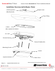
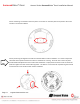
SurroundVideo® Omni Arecont Vision SurroundVideo® Omni Installation Manual Camera Alignment Tech Tip Alignment of the individual cameras is critical to setup. The individual cameras when placed on the circumference of the track must be in a counterclockwise sequence to create proper alignment when viewing the camera. Sensor 2 Sensor 3 Sensor 1 Sensor 4 Counterclockwise Sensor 3 Sensor 4 Sensor 2 Counterclockwise Page | 10 support@arecontvision.
SurroundVideo® Omni Arecont Vision SurroundVideo® Omni Installation Manual Installation 1. Wiring methods shall be in accordance with the National Electrical Code/NFPA 70/ANSI, and with all local codes and authorities having jurisdiction. Wiring should be UL Listed and/or Recognized wire suitable for the application. 2. Operating Temperature -40°C (-40°F) to +50°C (122°F) 3. Always use hardware e.g. screws, anchors, bolts, locking nuts etc.
SurroundVideo® Omni Arecont Vision SurroundVideo® Omni Installation Manual Focusing the Cameras Tech Tip Page | 12 1. Open a live view of the camera from your web browser or the AV Software provided (AV200). 2. Loosen the lens lock screw using a phillips head screwdriver (if necessary). Only do so if lens seems very tight when turning. Lock screw should be tightened enough to provide some friction against the lens to avoid focusing problems. 3.
SurroundVideo® Omni Arecont Vision SurroundVideo® Omni Installation Manual Changing the Lens 1. Remove the Dome Cover by loosening the captive fasteners as shown in Image 1. 2. Loosen the lens lock screw using a phillips head screwdriver (if necessary) as shown in Image 2. Only do so if lens seems very tight when turning. 3. Manually unscrew the lens, this may take several seconds as shown in Image 3. 4. Replace lens as shown in Image 4. 5. Retighten the lock screw if necessary as shown in Image 5. 6.
SurroundVideo® Omni Arecont Vision SurroundVideo® Omni Installation Manual Focusing Alternate Lenses When focusing the 6mm, 8mm, 12mm or 16mm lens options you will encounter a focus shift when using the bubble. To account for this follow these steps: Tech Tip 1. 2. 3. 4. Focus the camera without the bubble. Rotate the lens per the chart below. The rotation will account for most of the focus shift. Put cover with bubble on. You should be close to being focused.
SurroundVideo® Omni Arecont Vision SurroundVideo® Omni Installation Manual Digital Input and Output Use 4 position connector inside camera housing to interface with Digital I/O. DIGITAL I/O BLACK IN WHITE IN + YELLOW OUT ORANGE OUT + Electrical Characteristics Input Voltage (V) (Measured between + and – terminals) Output Current (mA) (Measured between + and – terminals) Applied Voltage Range : 0-80V MIN MAX ON 2.9 6.3 OFF 0 1.3 ON - 50 OFF - 0.
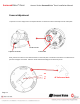
SurroundVideo® Omni Arecont Vision SurroundVideo® Omni Installation Manual Auxiliary Power If the camera is powered by a separate outside AC or DC power source, run the supplied power cable through the access hole on the camera housing and connect the power cable to the 2-position connector on the main camera board. The approximate location of the 2-position connector is circled in red below.
SurroundVideo® Omni Arecont Vision SurroundVideo® Omni Installation Manual LED Indicators LED Yellow Status Flashing Green Solid None Flashing Solid None Page | 17 support@arecontvision.com Description Link has been established. Normal Operation. No connection. Camera has been accessed. Normal operation. N/A No Connection.
SurroundVideo® Omni Arecont Vision SurroundVideo® Omni Installation Manual Support Arecont Vision FAQ Page Located at ArecontVision.com Check the following before you call: Restore camera to factory default with AV100, AV200 or the camera webpage. Upgrade to the latest firmware by visiting ArecontVision.com. Isolate the camera on a dedicated network and test with AV100 or AV200. Swap the “troubled” camera with a known good camera to see if the problem follows the camera or stays at the location.
SurroundVideo® Omni Installation Best Practice Begin Installation Adding Teflon thread sealing tape to all male threads Wind Vinyl electrical tape on all cables connections Connect ¾” NPT conduit pipe to junction box adapter No Does conduit pipe go through the wall? Yes Make sure position of conduit hole is at the lower side forming a “drip loop” below the camera using ¾” galvanized or flex conduit and appropriate fittings Tighten all camera screws and ¾” NPT plugs Caulk the perimeter of the mountin
SurroundVideo® Omni Arecont Vision SurroundVideo® Omni Installation Manual Camera Discovery, Setup, and Configuration For camera discovery and setup please use Arecont Vision software AV200 which you can find on the CD included with your camera or at: http://www.arecontvision.com/softwares.php The user manual for the AV200 software is included on the CD and is also located on our website. To configure the camera use either the AV200 software or the web interface utility.
SurroundVideo® Omni Arecont Vision SurroundVideo® Omni Installation Manual Wall Mount Accessory (AV-WMJB) Gasket -1.5” NPT Gasket Installation Notes: 1. 4x mounting screws are #10x1” wood or sheet metal screws (4x mount anchors also included). 2. Always ensure gaskets are properly seated. 3. Use Teflon tape on threaded interfaces. Page | 21 support@arecontvision.
SurroundVideo® Omni Arecont Vision SurroundVideo® Omni Installation Manual Pendant Mount Accessory (AV-PMJB) Gasket Installation Notes: Gasket 1. 4x mounting screws are #10x1” wood or sheet metal screws (4x mount anchors also included). 2. Always ensure gaskets are properly seated. 3. Use Teflon tape on threaded interfaces. -1.5” NPT Page | 22 support@arecontvision.
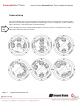
SurroundVideo® Omni Mount Template Page | 23 support@arecontvision.
SurroundVideo® Omni Arecont Vision SurroundVideo® Omni Installation Manual Troubleshooting Before troubleshooting, please visit http://www.arecontvision.com/ and check to ensure your camera has the most current and correct firmware version. Problem Possible Cause Lenses face the bubble crease, and the angle between Lenses and bubble is not perpendicular.
SurroundVideo® Omni Image quality problems Arecont Vision SurroundVideo® Omni Installation Manual Day/Night switch failure caused by turning lenses backward X: Ensure lens is oriented correctly O: or Day/Night switch failure Captive Fastener Page | 25 support@arecontvision.
SurroundVideo® Omni Arecont Vision SurroundVideo® Omni Installation Manual Contact Arecont Vision Technical Support one of three ways: Online Portal : Support.ArecontVision.com Phone : 1.818.937.0700 (option #1) Email : support@arecontvision.com Page | 26 support@arecontvision.