Surrou undVideo® Omn ni INST TALL LATIO ON MA ANUAL L AV12176DN-NL AV12176DN-28 AV12176DN-08 AV20175DN-NL AV20175DN-28 AV20175DN-08
SurroundVideo® Omni Arecont Vision SurroundVideo® Omni Installation Manual MicroDome™ Surface Mount Installation Contents Package Contents ....................................................................................................................................................... 3 Warranty Information ................................................................................................................................................ 4 Installation Overview ..........................
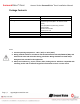
SurroundVideo® Omni Arecont Vision SurroundVideo® Omni Installation Manual Package Contents Item MegaPixel Camera Mounting Kit Power Cable I/O Cable Arecont Vision CD Description SurroundVideo® Omni Ceiling template 3x Mounting Screws (#6x1” for wood or sheet metal) 3x Drywall/Masonry Mounting Anchors Ceiling Gasket Network Patch Cable Security Torx Tool Aux Power Cord Digital Input and Output Adapter Manual, Warranty, Installation Software Notes: 1.
SurroundVideo® Omni Arecont Vision SurroundVideo® Omni Installation Manual Warranty Information 3 Year Limited Warranty ARECONT VISION warrants to Purchaser (and only Purchaser) (the “Limited Warranty”), that: (a) each Product shall be free from material defects in material and workmanship for a period of thirty-six (36) months from the date of shipment (the “Warranty Period”); (b) during the Warranty Period, the Products will materially conform with the specification in the applicable documentation; (c)
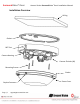
SurroundVideo® Omni Arecont Vision SurroundVideo® Omni Installation Manual Installation Overview Ceiling Gasket NPT Port Camera Housing Camera Gimbals (4X) Mounting Screws Gasket Captive Fasteners Page | 5 support@arecontvision.
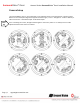
SurroundVideo® Omni Arecont Vision SurroundVideo® Omni Installation Manual Camera Setup The SurroundVideo® Omni is user configurable. Each individual sensor can be positioned in a variety of ways. Below are some example configurations (top left to bottom right) 1. 270° 2. Straight Line 3. 360° or Hallway 4. 180° or Panoramic 5. Random Example 6. Random Example. Tech Tip Page | 6 Prior to installing the camera, thought should be given to the sensor positions.
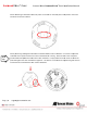
Surro oundVid deo® Om mni Arecont Vision V SurrroundVideo o® Omni In nstallation Manual Camera Adjusstment To positio on a sensor simply loosen the t captive faastener to rel ease the cam mera assemblyy from the traack plate. Captive Fastener F Track Platte Next, position the cam mera in the de esired location n on the trackk plate. Screw w holes aroun nd the circum mference are spaced in 5 degree increments. Note the arrowss marked at 445 degrees ass reference po oints.
Surro oundVid deo® Om mni Arecont Vision V SurrroundVideo o® Omni In nstallation Manual Sensor nu umbering is in ndicated on th he track plate e. The numbeer on the tracck plate correesponds to the sensor number in n the camera software. Tech Tip Page | 8 Sensor po ositioning and d alignment sh hould be considered beforre camera insstallation. It iis easier to ad djust the individuall camera positions before the camera iss installed intto a ceiling.
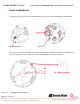
Surro oundVid deo® Om mni Arecont Vision V SurrroundVideo o® Omni In nstallation Manual Camera Alignment Tech Tip Alignment of the individual cameras is critical to setup. The i ndividual cam meras when p placed on thee circumferrence of the track must be in a countercclockwise seqquence to creeate proper alignment wheen viewing the camera. Senso or 2 Sensor 3 Seensor 1 Sensor 4 Co ounterclockwise Senssor 3 Sensor 4 Seensor 2 Coun nterclockw wise Senssor 1 Page | 9 supportt@arecontviision.
SurroundVideo® Omni Arecont Vision SurroundVideo® Omni Installation Manual Installation 1. Wiring methods shall be in accordance with the National Electrical Code/NFPA 70/ANSI, and with all local codes and authorities having jurisdiction. Wiring should be UL Listed and/or Recognized wire suitable for the application. 2. Operating Temperature ‐40°C (‐40°F) to +50°C (122°F) 3. Always use hardware e.g. screws, anchors, bolts, locking nuts etc.
SurroundVideo® Omni Arecont Vision SurroundVideo® Omni Installation Manual Focusing the Cameras Tech Tip 1. Open a live view of the camera from your web browser or the AV Software provided (AV200). 2. Loosen the lens lock screw using a phillips head screwdriver (if necessary). Only do so if lens seems very tight when turning. Lock screw should be tightened enough to provide some friction against the lens to avoid focusing problems. 3.
Surro oundVid deo® Om mni Arecont Vision V SurrroundVideo o® Omni In nstallation Manual Focusing Alternate Le enses When foccusing the 6m mm, 8mm, 12m mm or 16mm m lens optionss you will enco ounter a focu us shift when using the bubble. To T account for this follow these t steps: Tech Tip 1. 2. 3. 4. Fo ocus the camera without the t bubble. Rotate the lens per the chart below. The e rotation wi ll account forr most of the focus shift. h bubble on. You Y should be close to beiing focused.
SurroundVideo® Omni Arecont Vision SurroundVideo® Omni Installation Manual Digital Input and Output Use 4 position connector inside camera housing to interface with Digital I/O. DIGITAL I/O BLACK IN ‐ WHITE IN + YELLOW OUT ‐ ORANGE OUT + Electrical Characteristics Input Voltage (V) (Measured between + and – terminals) Output Current (mA) (Measured between + and – terminals) Applied Voltage Range : 0‐80V MIN MAX ON 2.9 6.3 OFF 0 1.3 ON ‐ 50 OFF ‐ 0.
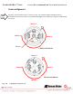
SurroundVideo® Omni Arecont Vision SurroundVideo® Omni Installation Manual Auxiliary Power If the camera is powered by a separate outside AC or DC power source, run the supplied power cable through the access hole on the camera housing and connect the power cable to the 2‐position connector on the main camera board. The approximate location of the 2‐position connector is circled in red below.
SurroundVideo® Omni Arecont Vision SurroundVideo® Omni Installation Manual LED Indicators LED Yellow Status Flashing Green Solid None Flashing Solid None Page | 15 support@arecontvision.com Description Link has been established. Normal Operation. No connection. Camera has been accessed. Normal operation. N/A No Connection.
SurroundVideo® Omni Arecont Vision SurroundVideo® Omni Installation Manual Support 1. Arecont Vision FAQ Page Located at ArecontVision.com 2. Check the following before you call: Restore camera to factory default with AV100, AV200 or the camera webpage. Upgrade to the latest firmware by visiting ArecontVision.com. Isolate the camera on a dedicated network and test with AV100 or AV200.
SurroundVideo® Omni Arecont Vision SurroundVideo® Omni Installation Manual Camera Discovery, Setup, and Configuration For camera discovery and setup please use Arecont Vision software AV200 which you can find on the CD included with your camera or at: http://www.arecontvision.com/softwares.php The user manual for the AV200 software is included on the CD and is also located on our website. To configure the camera use either the AV200 software or the web interface utility.
Surro oundVid deo® Om mni Arecont Vision V SurrroundVideo o® Omni In nstallation Manual Wall Mount M Accessor A ry (AV‐W WMJB) Gasket G Gasket Installattion Notes: 1. 4x 4 mountin ng screws are a #10x1” wood or ssheet metaal screws (4x mount anchors also include ed). 2. Always A ensure gasketts are prop perly seatedd. 3. Use U Teflon tape on th hreaded intterfaces. Page | 18 suppo ort@arecontv vision.
Surro oundVid deo® Om mni Arecont Vision V SurrroundVideo o® Omni In nstallation Manual Pendaant Mou unt Accessory (A AV‐PMJB B) Gaskket Installation Notes: Gaasket ounting scrrews are #10x1” 1. 4x mo wood d or sheet m metal screw ws (4x moun nt anchors also includ ded). 2. Alwayys ensure ggaskets aree properly seated. 3. Use TTeflon tapee on thread ded interffaces. Page | 19 suppo ort@arecontv vision.
SurroundVideo® Omni Arecont Vision SurroundVideo® Omni Installation Manual Mount Template Page | 20 support@arecontvision.
SurroundVideo® Omni Arecont Vision SurroundVideo® Omni Installation Manual Contact Arecont Vision Technical Support one of three ways: Online Portal : Support.ArecontVision.com Phone : 1.818.937.0700 (option #1) Email : support@arecontvision.com Page | 21 support@arecontvision.