ConteraIP ® Omni LX Remote Setup Installation Manual 8MP 20MP AV8476RS AV20476RS +1.818.937.0700 www.avcostar.com avsales@arecontvision.
Table of Contents About Our Warranty ...................................................................................................................................... 2 Global (3 Year) Limited Warranty ............................................................................................................. 2 Camera Overview ......................................................................................................................................... 3 Package Contents ....................
About Our Warranty Global (3 Year) Limited Warranty ARECONT VISION COSTAR warrants to Purchaser (and only Purchaser) (the “Limited Warranty”), that: (a) each Product shall be free from material defects in material and workmanship for a period of thirty-six (36) months from the date of shipment (the “Warranty Period”); (b) during the Warranty Period, the Products will materially conform with the specification in the applicable documentation; (c) all licensed programs accompanying the Product (the “Licensed P
Camera Overview The ConteraIP® Omni LX Remote Setup (RS) is an industry-game-changing first-of-its-kind omnidirectional, remote-configurable, multi-sensor, multi-megapixel camera built to provide outstanding highresolution video coverage for a wide range of applications.
Package Contents • AV8476RS / AV20476RS Description AV8476RS / AV20476RS IP camera Mounting Template Accessory Pack ConteraIP® Omni LX RS Installation Manual QTY 1 1 1 4
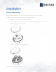
Installation Surface Mounting We recommend placing the ConteraIP® Omni LX RS camera directly on the hard ceiling. Template, anchors and screws are provided for mounting the camera. 1. Determine a secure location to mount the camera. 2. Use the supplied security L-key to loosen the four screws securing the dome cover. Do not remove screws from the dome cover. 3. Remove and discard the protective foam.
4. Reattach the dome cover to the camera. 5. If the 180°, 270°, or 360° preset configurations are being used, orient the camera such that the arrow denoting the front of the camera is pointing towards the center of the desired field of view. 6. Attach the mounting plate to the ceiling using the supplied mounting hardware.
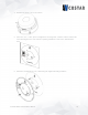
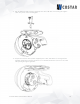
7. Attach the camera to the mounting plate as shown in the image below. The camera will “hang” from the hinge once properly attached. 8. Use a Phillips head screwdriver to loosen the three (3) screws on main housing cover to access the network port.
. Run the Ethernet Cable (and the supplied power cable, I/O cable if necessary) through the cable entry holes on the mounting plate. 10. Prepare the network cable (and the supplied power cable, I/O cable if necessary) with the supplied grommets by using the insertion tool or terminate the RJ-45 connector to the cable after passing through the grommet.
NOTE: The supplied grommet is required when mounting the camera outdoors or in a wet environment. Ensure the grommet properly seats flush with the camera housing to create a water-tight seal. 11. Connect the network cable (and the supplied power cable, I/O cable if necessary) to the corresponding connectors inside the camera.
12. Align the holes on main housing cover with the holes on mounting plate, and then install the main housing cover back on the camera. NOTE: If using the side connection of the NPT port, you need to install the supplied grommet without a hole on the main housing cover, and then remove the cap covering the side entrance, otherwise; leave the cap in place. If using the NPT port, always use Teflon tape around the threads to ensure proper sealing. The conduit fits ¾” NPT standard.
13. Use the supplied security L-key to attach the camera to the mounting plate. 14. Swing the camera up into place, and then use a Phillips head screwdriver to the camera to the mount plate. Use caution to not bend or pinch the cables during this step. 15. Secure the cover plate as shown in the image below. 16. Remove the protective film at the end to avoid leaving fingerprints, scratches, or any damage on the dome cover during the installation.
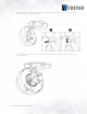
Pendant Mount Reference # Pendant Mount Components Required 1 Pendant mount (AV-PMJB-W) with an integrated junction box 2 ConteraIP® Omni LX RS camera 3 CORS-CAP-W mounting cap For a proper pendant mount installation, the AV-PMJB-W pendant mount and CORS-CAP-W mounting cap are required (sold separately). 1. Determine a proper location to place the ConteraIP® Omni LX RS camera. 2. Use the mounting template, and prepare the mounting provisions. 3. Connect CORS-CAP-W, pendant pole and mount together.
4. Attach the pendant mount to the ceiling using the 4 wood screws are provided for mounting or other optional hardware. 5. Run the ethernet cable and outside power cable (if necessary) through the rubber gasket which is supplied through the pendant mount. Ensure the gasket is sealed properly. 6. Use the L-key to loosen the four torx-in screws which are provided to secure the dome cover. 7. Remove the dome cover and the protective foam in the middle. Do not remove the torx-in screws from the dome cover.
10. Attach the mounting plate to the CORS-CAP-W with the screws which are supplied. 11. Follow the same steps as Surface Mount Installation to complete the installation. To configure the camera, reference the Camera Discovery, Set-up and Configuration section.
Wall Mount Reference # Required Wall Mount Components 1 Wall mount (AV-WMJB-W) with an integrated junction box 2 ConteraIP® Omni LX RS camera 3 CORS-CAP-W mounting cap For a proper wall mount installation, the AV-WMJB-W wall mount and CORS-CAP-W wall mount cap are required (sold separately). 1. Determine a proper location to place the ConteraIP® Omni LX RS camera. 2. Use the mounting template, and then prepare the mounting provisions. 3. Connect CORS-CAP-W cap and wall mount together.
5. Run the ethernet cable and outside power cable (if necessary) through the rubber gasket which is supplied, then let them pass through the wall mount. Ensure the gasket is sealed properly. 6. Use the L-key to loosen the four torx-in screws which are provided to secure the dome cover. 7. Remove the dome cover and the protective foam in the middle. Do not remove the torx-in screws from the dome cover. 8. Reattach the dome cover to the camera.
9. Attach the mounting plate to the CORS-CAP-W with the screws supplied. 10. Follow the same steps as Surface Mount Installation to complete the installation.
Pole Mount Reference # Required Pole Mount Components 1 Wall mount (AV-WMJB-W) with integrated junction box 2 ConteraIP® Omni LX RS camera 3 CORS-CAP-W mounting cap 4 AV-PMA-W pole mount adapter For a pole mount installation, AV-WMJB-W wall mount, AV-PMA-W pole mount, and CORS-CAP-W mount cap are required (sold separately). 1. Use the mounting template, and then prepare the mounting provisions. 2. Connect the wall mount cap and wall mount together. 3.
4. Remove the conduit plug on the junction box adapter, then connect ¾” NPT conduit to the junction box adapter. Reference # Description 1 Remove conduit plug 2 Connect ¾” NPT conduit to junction box adapter (Recommended: use of waterproof tape) NOTE: Use silicon or water pipe seal tape to make sure there is no water leakage between conduit pipe and junction box adapter. 5.
Corner Mount Reference # Required Corner Mount Components 1 Wall mount (AV-WMJB-W) with an integrated junction box 2 ConteraIP® Omni LX RS camera 3 CORS-CAP-W mounting cap 4 AV-CRMA-W corner mount adapter For a corner mount installation, the AV-WMJB-W wall mount, AV-CRMA-W corner mount, and CORS-CAP-W mount cap are required (sold separately). 1. Use the mounting template and prepare the mounting provisions. 2. Connect the wall mount and the wall mount cap together. 3.
Reference # Description 1 Remove the conduit plug. 2 Connect ¾” NPT conduit to junction box adapter (ensure to use the waterproof tape). NOTE: Use silicon or water pipe seal tape to make sure there is no water leakage between conduit pipe and junction box adapter. 5. Run the ethernet cable and outside power cable (if necessary) through the rubber gasket which is supplied, then pass through the Junction Box Adapter and AV-WMJB-W, Wall Mount Adapter. Ensure the gasket is sealed properly. 6.
Camera Power Up 1. Connect the camera to a PoE+ port on 1000Mbps network PoE+ switch using an Ethernet cable. 2. If the camera is powered by an external power supply12V DC or 24V AC must be supplied.
3. Connect the PoE+ switch to your computer’s network port by using an ethernet cable.
Alarm I/O Functions Connect the Alarm In (DI) connector to the alarm input sensor, and then connect the Alarm Out (DO) connector to the alarm output signal. To avoid any damage, please follow the specification of the part as below: Alarm In (Wet Contact) 50mA (max) 3.
Reset to Factory Default 1. Press and hold the reset button for 2 to 5 seconds, then release the reset button. This resets the camera to the factory default except for the network settings. 2. Press and hold the reset button for more than 5 seconds, then release the reset button. This resets the camera to the factory default, and this resets the network settings to the factory default. 3. Also, the user can reset the camera to factory default via the camera web interface or AV IP Utility.
Audio/SD Card Info • SD Card Slot • Audio Connector ConteraIP® Omni LX RS Installation Manual 26
Camera Discovery, Setup, and Configuration AV IP Utility is recommended for camera discovery and setup. Software can be found on the website of Arecont Vision Costar http://www.arecontvision.com/softwares.php. The AV IP Utility can provide multiple discovery options including broadcast and multicast, check the status of a camera, change the camera settings, import and export camera settings via a .csv file, and update firmware and/or hardware from virtually anywhere with a network connection.
Camera Discovery 1. Locate and double click the AV IP Utility shortcut on the desktop. 2. When the AV IP Utility is launched, it will automatically search the ConteraIP® cameras on the network. Also, you can manually search the camera by clicking “Discovery (Multicast)” 3. You can access the camera’s web interface by typing the camera IP address on the preferred web browser. 4. If there is no DHCP server present in the network, the camera will default to the following IP Address “192.168.1.168”.
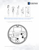
Camera Preset Configurations The Arecont Vision Costar ConteraIP® Omni LX RS camera supports three (3) predifined camera preset configurations: 180 degrees, 270 degrees, and 360 degrees. Also, the camera supports two custom preset configurations. • Home position Four camera modules will move to the position as the image below. All four modules zoom out to widest angle, and tilt up to zero degree.
• 180 degrees preset configuration Four camera modules will move to the positions as the image below. CH1/2/3 zoom in to 60 degrees H-FOV, and tilt down to 37 degrees. CH4 zooms out to widest angle, and tilt down to 135 degrees. • 270 degrees preset configuration Four camera modules will move to the positions as the image shown. CH1/2/3 zoom in to 90 degrees H-FOV, and tilt down to 37 degrees. CH4 zooms out to widest angle, and tilt down to 135 degrees.
• 360 degrees preset configuration Four camera modules will move to the positions as the image below. All four modules zoom in to 90 degrees H-FOV, and tilt down to 37 degrees.
User can define custom pan/tilt/zoom positions as the image below. 1. To control the camera preset configurations via the web interface: a. Double click the camera within the AV IP Utility (image below). b. Open your preferred web browser and type the camera’s IP address (displayed inthe image below) 2. Click Presets Tab NOTE: ConteraIP® Omni LX RS camera is not used as traditional high speed PTZ camera. The motorized movement of the camera gimbals is meant for setup and configuration only.
ConteraIP® Omni LX RS Installation Manual 33
Home Position / 360 Degrees Preset Configuration 1. In the “Preset buttons” section, click “Home” or “360”. 2. To make an adjustment on all four camera modules without selecting each camera module individually; you can select “1-4” from the drop list. 3. For individual adjustment on each camera module, select the “Focus/PTZ” tab.
NOTE: ConteraIP® Omni LX RS camera is not used as traditional high speed PTZ camera. The motorized movement of the camera gimbals is meant for setup and configuration only. Movement of the modules more than one time per day will void the warranty. NOTE: Module CH2 will not pass the FRONT position shown on the mounting plate. This is to avoid cable routing problems.
180 / 270 Degrees Preset Configuration 1. In the “Preset buttons” section, click “180” or “270” 2. To make an adjustment to the entire panoramic configuration (without having to select each camera module individually) you can select “1/2/3” from the drop-down menu. Doing this will allow you to modify the entire panoramic configuration.
3. To individually adjust each camera module, select the “Focus/PTZ” tab. NOTE: ConteraIP® Omni LX RS camera is not used as traditional high speed PTZ camera. The motorized movement of the camera gimbals is only for setup and configuration. Movement of the modules be made more than one time per day will void the warranty. NOTE: Module CH2 will not pass the FRONT position shown on the mounting plate. To avoid the cable routing problems.
Create Custom Preset Configuration 1. In “Preset buttons” section, click “Create Preset 1” or “Create Preset 2”. 2. To adjust Focus/Pan/Tilt/Zoom positions for individual module or all four modules via Channel Selects. 3. Once the user has a desired position for each module, click “Save Preset 1” or “Save Preset 2”.
4. Click “User Preset 1” or “User Preset 2” to get the custom preset configuration which is setup by the user. NOTE: ConteraIP® Omni LX RS camera is not used as traditional high speed PTZ camera. The motorized movement of the camera gimbals is only for setup and configuration. Movement of the modules be made more than one time per day will void the warranty. NOTE: Module CH2 will not pass the FRONT position shown on the mounting plate. To avoid the cable routing problems.
Web Interface Navigation The entire menu is located on the top of the web interface. The following camera settings are available on the top of the menu in the web interface, and the user will be directed to the page that they click on the menu.
Ports DNS o IPv6 Settings • QoS (Quality of Service) • UPnP (Universal Plug and Play) • RTSP (Real Time Streaming Protocol) • DDNS (Dynamic DNS) • SNMP (Simple Network Management Protocol) • SSL (Secure Sockets Layer) • FTP (File Transfer Protocol) • 802.
1. At the left corner on the top, you can see the “Flip” button that allows you to rotate the images up-sidedown (180 degrees) with reorienting the channel order. 2. You will be able to see the Channel number when you move the mouse over the image of the channel.
Image Menu Feature Global Mode Brightness Description Enable Global Mode (ON) Set up the parameters for four channels together. If Global Mode is enabled, the settings of four channels will be the same and they can be adjusted together. Disable Global Mode (OFF) Set up the parameters for each channel independently. If Global Mode is disabled, you can select the desired channel from “Select channel” to change settings.
AE Mode (Auto Exposure Mode) Sync Brightness: This option is available only if Global Mode is enabled. If Sync Brightness is selected, the Exposure Time Control and Gain Control are the same for all four channels. Also, the camera will be in LDR mode. Auto: If Auto is selected, each channel has individual settings of the Exposure Time Control and Gain Control.
Stream Profiles: Balance Mode -Slow Shutter Quality Mode Balanced Mode: Limits exposure time from 0.1ms to 66ms. The camera will keep highest FPS when Slow Shutter is unchecked. Quality Mode: Limits exposure time from 0.1ms to 200ms. This mode is a good compromise between reducing noise and motion blur under most lighting conditions, but with an increase in motion blur under low light conditions. Moonlight Mode Custom Exposure Mode Moonlight Mode: Limits exposure time from 20ms to 500ms.
ConteraIP® Omni LX RS Installation Manual Background Translucent Transparent Configures the background color of the text overlay. The options are Translucent (light grey) or Transparent. Text Color Options are Black, White, Green, or Yellow. Text Overlay Off Date/Time Camera Name Camera Name + Date/Time Custom Text There are four content positions (Top Left, Top Right, Bottom Left and Bottom Right) to display the text overlay. Date / Time: Displays the current date/time.
ROI (Regions of Interest) ConteraIP® Omni LX RS Installation Manual ROI (Regions of Interest) is used to select which areas will be monitored and recorded with higher image quality while using lower image quality for other non-ROI zones in order to save bandwidth and storage. To setup the ROI: 1. Select the desired channel 2. Select Main Stream or Sub Stream 3. Enable zones (up to five zones) and select the desired quality level (High, Medium, or Low) 4.
Video & Audio Menu Feature Select channel Description Select the desired channel to change video settings or select Sync All Channels to change video settings for all four channels at once. Video Compression: H.265 / H.264 Resolution Radio buttons to select the desired compression. Radio buttons to select the desired resolution. Options vary based on the sensor resolution being used. Enable the SNAPstream+ TM feature on the camera.
GOP Length Video Compression: MPJEG Resolution Frames Per Seconds Quality: Low / Mid / High Video Compression: MPJEG Audio In Audio Out Volume Encoding ConteraIP® Omni LX RS Installation Manual Specifies how many frames exist between two consecutive I-Frames. The third stream is designed for the live view on web interface, and the only option of Video Compression is MPJEG. The third stream is designed for the live view on web interface, and the only option for Resolution is VGA.
Network Menu Feature IP Assignment: • DHCP • IP Address • Subnet Mask • Default Gateway Port: • • • Port: • • HTTP Second HTTP Port HTTPs Primary DNS Secondary DNS IPv6 Settings: • Enable IPv6 • IPv6 Address • Address Prefix • Default Route • Router Advertisement • DNS ConteraIP® Omni LX RS Installation Manual Description DHCP: If checked, the camera will attempt to obtain its IP address from the DHCP server available on the network. IP Address: Sets the current IP address of the camera.
QoS Enable Enables quality of service. QoS Video Sets DSCP value for video traffic. Management DSCP Sets DSCP value for non-video traffic. Enable UPnP Enables Universal Plug and Play function.
Path TTL Enable DDNS Host Name DDNS Sever User Name Password Password Confirmation No SNMP Sever SNMP v2c Community String Trap Configuration: Address Community String SNMP v3 SNMP User Selects one of the pubic DDNS severs from the dropdown menu. Options are DynDNS, NO-IP, and Twi-DNS. Specifies the user name of the DDNS account. Specifies the password of the DDNS account. Confirms the password of the DDNS account.
Install New Certificate Key PEM file Certificate PEM file 1. 2. ConteraIP® Omni LX RS Installation Manual Locate Key PEM file and Certificate PEM file and click Upload. Click Install New Certificate to upload the Certificate. Enable Enables FTP access to the camera. Password Confirm NOTE: This function is only available when a SD card is installed. You can access files in the SD card via FTP. Specifies and confirms the password to access the FTP. Max.
Privacy Mask Menu Feature Enable Privacy Mask Select Channel Drag mouse to: Mask Unmask ConteraIP® Omni LX RS Installation Manual Description Creates a privacy mask on the image so the selected areas will not be visible. Select the desired channel to add privacy masks. Select Mask to add privacy masks or Select Unmask to remove privacy masks.
Event Menu Event > Motion Detection Feature Enable motion detection Enable extended motion detection Select channel Zone Size Object Size Sensitivity Movement Duration Factor Motion Sensitivity Enable Alarm Detection ConteraIP® Omni LX RS Installation Manual Description Turn on and off on-camera motion detection. Enables the extended motion detection and motion detection zones with an increase from default 64 to 1024 for enhanced motion detection sensitivity.
Event > Alarm Handler Event > Digital I/O Alarm Schedule Trigger Alarm Detection Trigger Motion Detection Trigger Tamper Detection Trigger Network Failure Type Off Time Specifies the alarm duration Select channel Select the desired channel to enable tampering detection. Enables Tampering Detection function.
Sensitivity Enable Network Failure Event > SD Card SD Record Handler Enable Enables and selects a desired trigger source. The options are Trigger Alarm Detection, Trigger Motion Detection, Trigger Tampering Alarm, Trigger Network Failure, and Manual Record. SD Card Information Available Storage: Displays the available storage of the SD card if it is installed. Format SD Card: Erases all the data stored on the SD Card. Usage: Displays the total storage that has been used now.
Event > SMTP Notification Host Address Host Address: Specifies the host name or IP address of the FTP server. Port Port: Specifies the port number of the FTP server. Username Username: Specifies the login username of the FTP server. Password Password: Specifies the login password of the FTP server. SMTP Notification Handler From: Specifies the email address of the sender Selects a desired trigger source.
Network Storage Status Network Address Folder Name Record Type Login Certificate Mount Network Storage Remove Network Storage ConteraIP® Omni LX RS Installation Manual the network storage server. (Status will display “Not Mounted” or “OK”) Network Address: Specifies the IP address of the network storage server. Folder Name: Specifies the folder name on the network storage server. Recoding Type: Specifies the desired action when an event is triggered. The options are Snapshot and Video.
System Menu Feature Firmware Upgrade Download Log • Reboot the Camera • Restore Factory Default Settings Except Network Settings • Restore to Factory Default Settings Camera information Date/Time • Get Time from • NTP Server • Computer System Description Clicks “Choose File” to choose the firmware upgrade file, and then click Upgrade. Records all the status information of the camera in list format. Downloads the log file to the computer as a text file. NOTE: The log file is protected by a password.
Computer System: Synchronizes the date/time information with current computer’s date/time. Once this option is selected, click “Update Time from the computer”. Time Zone NTP Server ConteraIP® Omni LX RS Installation Manual Specifies the country / city of the time zone from the drop-down menu.
Administration Menu Feature Access Control Administrator • Username • Admin Password • Confirmation • Set/ Erase Viewer Management • User List ConteraIP® Omni LX RS Installation Manual • User Viewer Name • • User Viewer Password Confirmation • Access Level • Set/ Erase Description Passwords can be up to 16 letters, digits and symbols, excluding the following symbols for passwords without encoding # % & ' " < > / [ ] { } _ ( )=.
Support Menu Feature Support ConteraIP® Omni LX RS Installation Manual Description Provides several hyperlinks to get more information on the camera.
© 2020 Arecont Vision Costar All rights reserved. No part of this publication may be reproduced by any means without written permission from Arecont Vision Costar. The information in this publication is believed to be accurate in all respects. However, Arecont Vision Costar cannot assume responsibility for any consequences resulting from the use thereof. The information contained herein is subject to change without notice.
Mounting Templates