Installation Manual Wide Angle Models: AV2225PMIR AV2225PMIR-A AV2226PMIR AV3225PMIR AV3226PMIR AV3226PMIR-A AV5225PMIR AV5225PMIR-A AV10225PMIR Telephoto Models: AV2225PMTIR AV2226PMTIR AV3225PMTIR AV3226PMTIR AV5225PMTIR AV10225PMTIR Telephoto Model Wide Angle Models
Arecont Vision MegaView® 2 Installation Manual MegaView® 2 Installation Contents Contents ................................................................................................................................................................... 2 Package Contents ................................................................................................................................................... 3 Warranty Information ..................................................................
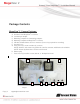
Arecont Vision MegaView® 2 Installation Manual Package Contents MegaView® 2 Camera Package: Arecont Vision MegaView® 2 Camera Junction box adapter Mounting Template for Junction box adapter Mounting Template for MegaView® 2 Camera CD with AV100 software and user manuals (license key required for recording) Security L-key Pack of four (4) screws and four (4) anchors NOTE: Anchors and screws are good to be used for concrete, wall block and red bricks. NOTE: Screws by themselves can be used in wood. H.
Arecont Vision MegaView® 2 Installation Manual Warranty Information 3 Year Limited Warranty ARECONT VISION warrants to Purchaser (and only Purchaser) (the “Limited Warranty”), that: (a) each Product shall be free from material defects in material and workmanship for a period of thirty-six (36) months from the date of shipment (the “Warranty Period”); (b) during the Warranty Period, the Products will materially conform with the specification in the applicable documentation; (c) all licensed programs accompa
Arecont Vision MegaView® 2 Installation Manual Install MegaView® 2 Camera Mounting the Camera: 1. Remove camera and hardware from the box. 2. Use the mounting template (Image 1-C), to prepare the mounting provisions for junction box adapter installation. NOTE 1: Water damage from improper installation is not covered by the warranty! NOTE 2: Use of silicon on the RJ45 connector without junction box adapter does not guarantee a water resistant install. ¾” NPT Pipe 3.
Arecont Vision MegaView® 2 Installation Manual NOTE 1: Bracket screws are all security screws that are tamper-resistant. NOTE 2: Bracket with 3 axes enables easy installation in any location, including 360° camera body rotation, 90° tilt, 360° bracket rotation. (Image 7) Image 4 8. Use the security L-key to adjust MegaView® 2 bracket to appropriate position. ( Image 5) 360° 360° 90° Image 7 NOTE 3: MegaView® 2 is a total PoE class 3 solution to power the camera, IR illuminator and fan. Fan is always on.
Arecont Vision MegaView® 2 Installation Manual Optional: Connecting Digital I/O: 9. To use digital I/O, connect digital I/O with pigtail cable connector as shown in Image 8. NOTE 1: MegaView® 2 only supports digital input but no digital output. Input voltage (V) (measured between + and – terminals) Min Max ON 2.9 6.3 OFF 0 1.3 OFF - 0.1 Table 1 NOTE 3: The digital input is electrically isolated from the rest of the camera’s electrical circuitry via general-purpose photo couplers.
Arecont Vision MegaView® 2 Installation Manual 16. To manually focus, click the “+20”, “+5”, “+1”, “-20”, “-5”, “-1” buttons to fine tune the focus. Image 9 Adjusting P-Iris: Note: If “Enable P-Iris” is unchecked, the iris will be fully open to the maximum. It may result in less sharpness and artificial color under strong light condition. Image 9-1 Page | 8 support@arecontvision.
Arecont Vision MegaView® 2 Installation Manual Optional: Enable Audio: 17. Connect a mono analog microphone to Microphone In and connect an active speaker with a built-in amplifier via the inline jack as shown in Image 8, if needed. 18. Choose “H.264 over RTP/UDP” as shown on Image 10-1 and check “Enable Microphone” then click “Preview” and “Apply” buttons as shown on Image 10-2. NOTE: Audio only works in H.264 RTP/UDP streaming Image 10-1 Page | 9 support@arecontvision.com Image 10-2 .
Arecont Vision MegaView® 2 Installation Manual Replacing the IR LED board: 19. Unscrew glass ring (Image 11) 20. Use Phillips screwdriver to remove IR LED board (Image 12) 21. To replace IR LED board, unplug cable and replace new IR LED board (Image 12-1) NOTE : 48pcs IR LED board for wide angle MV2: part number: M000094-34 4pcs IR LED board for tele photo part number: Image 12 M000094-38 Image 12-1 Image 11 Page | 10 support@arecontvision.
Camera Software Installation 22. Install the AV100 application manager Software. (Image 13, found on the CD). Installation Manual” (found on the CD) for details on Advanced Mode. 23. Run the AV100 application manager by double clicking on the icon shown below. (Image 14, found on your desktop). NOTE 2: Basic Mode: software will automatically discover and change / assign IP address to match PC subnet if they are not locked.
Arecont Vision MegaView® 2 Installation Manual NOTE : Double click the camera model on the Camera Installer as shown in Image 17 to access the camera web interface. See “AV Camera Web Page User Manual” (found on the CD) for details on the web interface. Image 17 29. When all cameras are discovered and display “Installed, online”, select “Save/Exit.” The AV100 application main menu will appear. 30. From the “AV100 Application Manager” menu, select “Run” next to “Live video” to view live images.
Electrical Box Adapter (SV-EBA) Installation Instructions (Sold Separately) Inside the box: A. Electrical Box Adapter B. Pack of four (4) machine screws (#8-32 7/16”) A ® MegaView 2 Bracket holes Image 18-1 Single gang box Junction box adapter holes B Image 18 Image 18-2 Double gang box Not included but needed: Common electrical box, such as single gang box, double gang box, or square electrical boxes shown in Image 18-1~4. 1. Remove the electrical box adapter and hardware from the box. 2.
Arecont Vision MegaView® 2 Installation Manual Pole Mount Adapter (AV-PMA) Installation Instructions (Sold Separately) Inside the box: A. B. C. D. Pole Mount Adapter 2x Small Steel Straps 2x Large Steel Straps Pack of four (4) machine screws (#8-32 5/8”) Not included but needed: ¾” NPT Conduit 5. Attach MegaView® 2 bracket to Pole Mount Adapter as shown in Image 21. 6.
Corner Mount Adapter (AV-CRMA) Installation Instructions (Sold Separately) Inside the box: A. Corner Mount Adapter B. Pack of four (4) machine screws (#8-32 5/8”), twelve (12) screws, twelve (12) anchors, and twelve (12) washers Not included but needed: ¾” NPT Conduit 4. Run Ethernet Cable and other cables (if necessary) through the Junction Box Adapter and connect to Megaview® 2 pigtail cable. 5. Attach MegaView® 2 bracket to Corner Mount Adapter as shown in Image 24. 6.
Arecont Vision MegaView® 2 Installation Manual Important Note How to correctly install MegaView® 2 on a surface wall Correct Installation: Please connect ¾” NPT conduit pipe to junction How to correctly install MegaDome® 2 on a ROUGH surface wall box adapter as shown in Image 25 and tighten ¾” NPT plugs to avoid water leakage on a surface wall as shown in Image 26. NOTE: Adding water seal tape on the thread of ¾” NPT pipe to avoid water leakage.
Arecont Vision MegaView® 2 Installation Manual Inappropriate Installation: Attaching the MegaView® 2 directly onto a wall surface as shown on Image 27, without connecting ¾” NPT Conduit to Junction Box Adapter as shown on Image 28, or without tightening ¾” NPT plugs as shown on Image 29 may result in water leakage! NOTE: Water damage from improper installation is not covered by the warranty! Not Recommended! Not Recommended! Junction Box Adapter Image 28 Image 27 Without connecting ¾” NPT Conduit N
Installation Best Practices Begin Installation Adding Teflon thread sealing tape to all male threads Wind Vinyl electrical tape on all cables connections Connect ¾” NPT conduit pipe to junction box adapter Does conduit pipe go through the wall? Yes No Make sure position of conduit hole is at the lower side forming a “drip loop” below the camera using ¾” galvanized or flex conduit and appropriate fittings Tighten all camera screws and ¾” NPT plugs Caulk the perimeter of the mounting area End Installa
LED Indicators (Camera Signal) NOTE: To see the LED indicators, open the plug on the camera body as shown in Image 30. Plug Image 30 LED Yellow Status Flashing Green Solid None Flashing Solid None Description Link has been established. Normal Operation. No connection. Camera has been accessed. Normal operation. N/A No Connection.
Arecont Vision MegaView® 2 Installation Manual Support 1. Arecont Vision FAQ Page Located at ArecontVision.com 2. Check the following before you call: Restore camera to factory default with AV100, AV200 or the camera webpage. Upgrade to the latest firmware by visiting ArecontVision.com. Isolate the camera on a dedicated network and test with AV100 or AV200. Swap the “troubled” camera with a known good camera to see if the problem follows the camera or stays at the location. 3.
Arecont Vision MegaView® 2 Installation Manual Mounting Template Junction Box Adapter Mounting Template Page | 21 support@arecontvision.