MicroDome® Duo Installation Manual Models: 4 Megapixel AV4655DN-08 AV4655DN-28 AV4655DN-NL 4 Megapixel WDR AV4656 DN-08 AV4656DN -28 AV4656DN-NL 6 Megapixel AV6655DN-08 AV6655DN-28 AV6655DN-NL 6 Megapixel WDR AV6656DN-08 AV6656DN-28 AV6656DN-NL 10 Megapixel AV10655DN-08 AV10655DN-28 AV10655DN-NL
Microdome Duo® Installation Manual Contents Models ................................................................................................................................................... 1 Package Content ................................................................................................................................... 3 Warranty Information .............................................................................................................................
Microdome Duo® Installation Manual CAUTION! 1. Do not attempt to service a damaged unit yourself. Refer all servicing to qualified service personnel. 2. Wiring methods shall be in accordance with the National Electrical Code/NFPA 70/ANSI, and with all local codes and authorities having jurisdiction. Wiring should be UL Listed and/or Recognized wire suitable for the application. 3. Always use hardware e.g. screws, anchors, bolts, locking nuts etc.
Microdome Duo® Installation Manual Warranty Information Global (3 Year) Limited Warranty ARECONT VISION warrants to Purchaser (and only Purchaser) (the “Limited Warranty”), that: (a) each Product shall be free from material defects in material and workmanship for a period of thirty-six (36) months from the date of shipment (the “Warranty Period”); (b) during the Warranty Period, the Products will materially conform with the specification in the applicable documentation; (c) all licensed programs accompany
Microdome Duo® Installation Manual Camera Overview The MicroDome Duo multi-sensor, multi-megapixel 2-dome cameras provide users with professional surveillance experience for a variety of network surveillance requirements. The MicroDome Duo multi-megapixel cameras series feature a choice of 4-, 6- or 10-megapixel resolution options, including 4- and 6-megapixel WDR options. These remote focus true day/night cameras are available with a choice of lenses including 2.8mm, 8mm or no lens options.
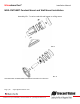
Microdome Duo® Installation Manual Surface Installation 1. Determine a secure location to mount the camera. 2. Use the supplied security L-key, to loosen the four (4) screws which secure the cover. PIC. 1 3. Remove the cover. Do not remove screws from the dome cover. 4. Use Phillips screwdriver to loosen the four (4) screws securing the camera to adapter plate. PIC. 2 (some parts removed for clarity) 5. Separate Camera from Adapter Plate Do not remove the screws. 6.
Microdome Duo® Installation Manual PIC. 3 PIC 4 8. Re-attach camera to adapter plate (Reverse step 4 and 5) 9. Re-attach cover to camera (Reverse step 2 and 3) Page | 7 support@arecontvision.com +1.818.937.0700 | 877.CAMERA.8 | www.arecontvision.com | avsales@arecontvision.
Microdome Duo® Installation Manual Drop Ceiling Mount Adapter Plate Installation Repeat step 1-5 of Surface Installation (See Pic. 1-3) 6. Use template and cable location to create mounting provisions for the Plate. Use 3/16” drill bits for four mounting holes in Drop Ceiling Panel. 7.
Microdome Duo® Installation Manual MDD-CAP Installation Repeat step 1-5 of Surface Installation (See Pic. 1-3) 6. Insert Adapter Plate into the Cap and attach it to the cap, using the 4 screws through 4 “A” holes using enclosed #6-32 screws. Adapter Plate Cap PIC 6. 7. Re-attach camera to adapter plate (Reverse step 4 and 5) 8. Re-attach cover to camera (Reverse step 2 and 3) PIC. 7 Page | 9 support@arecontvision.com +1.818.937.0700 | 877.CAMERA.8 | www.arecontvision.com | avsales@arecontvision.
Microdome Duo® Installation Manual MDD-CMT/WMT Pendant Mount and Wall Mount Installation Assembly (Pic. 7) can be used with wall mount or ceiling mount PIC 8 PIC. 9 Use MCD-CMT and MCD-WMT installation instructions for reference. Page | 10 support@arecontvision.com +1.818.937.0700 | 877.CAMERA.8 | www.arecontvision.com | avsales@arecontvision.
Microdome Duo® Installation Manual MDD-FMA Flush Mount Installation Note: MDD-FMA is designed for indoor use only. Grommet use is recommended. 1. Use template to cut the ceiling plate and create mounting provisions for the Flush Mount Ceiling Panel. PIC. 10 2. Use the supplied security L-key, to loosen the four (4) screws which secure the cover on camera. (See Pic. 1). Remove the cover. 3. Install Flush Mount Cover and tighten the four (4) screws which secure the Flush Mount Cover to camera. PIC.
Microdome Duo® Installation Manual 4. Plug PoE cable (not shown for clarity) 5. Hold all four latches as shown on PIC. 12 PIC. 12 6. Insert camera into cutout prepared in step 1 PIC. 13 Page | 12 support@arecontvision.com +1.818.937.0700 | 877.CAMERA.8 | www.arecontvision.com | avsales@arecontvision.
Microdome Duo® Installation Manual PIC. 14 7. Undo 4 screws shown and remove both Rings and Bubbles. PIC. 15 Bubbles Rings 8. Adjust Pan and Tilt for both modules as shown on page 14. 9. Re-attach Rings and Bubbles and tighten 4 screws from step 7. Page | 13 support@arecontvision.com +1.818.937.0700 | 877.CAMERA.8 | www.arecontvision.com | avsales@arecontvision.
Microdome Duo® Installation Manual Pan and Tilt Adjustment 1. Use the supplied security L-key, to loosen the four (4) screws which secure the cover. See Pic. 1. 2. Remove the cover. 3. Adjust the pan and tilt of each camera module to obtain the desired field of view. Do not to press the remote focus motor against the sides of camera module when adjusting the field of view (Pic. 5). PIC. 16 4.
Microdome Duo® Installation Manual Lens Replacement 1. Use the supplied security L-key, to loosen the four (4) screws which secure the cover. (See Pic. 1). Remove the cover. PIC. 18 2. Manually turn the lens counter clockwise, this may take several turns. 3. Screw the replacement lens clockwise until you feel some resistance and hit a hard stop. 4. Repeat for another camera module if necessary Page | 15 support@arecontvision.com +1.818.937.0700 | 877.CAMERA.8 | www.arecontvision.
Microdome Duo® Installation Manual Usage of Ethernet cable other than included M/F PoE cable. 1. Insert CAT 5E cable into Grommet Installation Tool as shown on Pic. 19. 2. If intend to use AC/DC power to power up the camera, insert the wire (not supplied) into grommet. See instructions on page 23 for cable preparation. 3. If intend to use I/O cable, insert the supplied cable into grommet. 4. Insert Ethernet Cable with Tool on it into the Grommet as shown.
Microdome Duo® Installation Manual Connecting Digital I/O 1. To use digital I/O use 5-wire pigtail cable (included) and plug it into I/O connector (Pic 13). The color coding is shown in Table 1 below PIC. 20 5-Pin I/O Connector PoE Connector AC/DC Connector Electrical Characteristics Input Voltage (V) (Measured between “+” and “–“ terminals) Output Current (mA) (Measured between “+” and “–“ terminals) Applied Voltage Range: 0-80V MIN MAX PIN I/O CABLE WIRE COLOR ON 2.9 6.
Microdome Duo® Installation Manual AUX I/O use case example Arecont Vision AUX I/O ALARM OUT+ ALARM OUT- + 120V 100mA (max) - D G ALARM-OUT S 3.3VO + Normally Open/Close - + - ALARM IN+ 250Ω ALARM IN- 0-12VDC 50mA (max) GND Page | 18 support@arecontvision.com +1.818.937.0700 | 877.CAMERA.8 | www.arecontvision.com | avsales@arecontvision.
Microdome Duo® Installation Manual OUTPUT Relay Control and Function The camera has an output for activating an external device. The camera supports both transient and continuous relay operation. You can operate the relay during an active connection using the API command set. Typical applications include turning on lights or activating doors and locks.
Microdome Duo® Installation Manual INPUT Alarm Control and Detection The input optocoupler supports two ways to connect external unsupervised alarms to Arecont Vision camera. Only one of the following two schemes should be used at any given time. OPTION-1: UNSUPERVISED ALARM DETECTION In this scheme the IN+ & IN- terminals can be used for external signaling devices, such as door contacts or motion detectors.
Microdome Duo® Installation Manual In this scheme the IN- & GND terminals can be tied to an external power source. The camera can detect a range of voltage to trigger an internal alarm on|off condition.
Microdome Duo® Installation Manual Camera Power Up using PoE This product should be installed by a qualified service technician in accordance with the National Electrical Code (NEC 800 CEC Section 60) or applicable local code. Make sure that your installation of wires complies with Electrical Code of the local government where the camera is installed and no bare wires are exposed. 1. Remove cover from the camera as described on page 6. 2.
Microdome Duo® Installation Manual Use of Auxiliary Power 1. If the camera is powered by a separate outside AC or DC power source, run the wire (not supplied) through the grommet and connect the power cable to the 4-position connector on the Main Board. (see Page 17 and 18 for illustration and detailed instructions) 2. The Poke-Home connector requires 18 AWG to 24 AWG wire (solid or stranded). 3.
Microdome Duo® Installation Manual Camera Discovery, Setup, and Configuration For camera discovery and setup, the AV IP Utility is recommended. The software can be found on the CD included with your camera or at: http://www.arecontvision.com/softwares.php. The AV IP Utility has the ability to provide multiple discovery options, including broadcast and multicast, check the status of a camera, change camera settings, import and export camera settings via a .
Microdome Duo® Installation Manual Network Protocols The Arecont Vision MicroDome Duo cameras support RTSP, RTP/TCP, RTP/UDP, HTTP, DHCP, TFTP, QoS, IP version 4 (IPv4) and IP version 6 (IPv6). RTSP Cameras communicate with video management systems over Real Time Streaming Protocol. Do not change the RTSP port unless you are sure your VMS does not use the default setting.
Microdome Duo® Installation Manual General Remote Focus 1. To control the remote focus via the web interface, double click the camera within the AV IP Utility (Figure 1) or open your preferred web browser and type the camera’s IP address (Figure 2). NOTE: For supporting H.264 streaming on a webpage, the recommended browsers are Internet Explorer and Firefox. Figure 1: Double click via AV IP Utility Figure 2: Type the camera IP address 2. Scroll to the Focus Tab section.
Microdome Duo® 5. Please complete the same action for Channel 2 by following steps 2 to 5. Page | 27 support@arecontvision.com +1.818.937.0700 | 877.CAMERA.8 | www.arecontvision.com | avsales@arecontvision.
Microdome Duo® Installation Manual AV IP Utility Focus Tab Menu Feature Description Manual Focus: +20, +5, +1, -20, -5, -1 Numbers indicate the level of focusing in order to adjust the field-of-view. Full-range Focus Best for scenes that are completely out of focus. The camera automatically scans the full focus range of the scene to find the best focus position. Short-range Focus Best for scenes that are slightly of out of focus. The camera quickly finetunes for a precise focus position.
Microdome Duo® Installation Manual Administration and Password Setting Administration is the place to set a password. Arecont Vision cameras support two levels of passwordprotected access control. Camera authentication is compatible with RFC-2068 HTTP 1.1 and is supported by all standard browsers and video surveillance software. A. There are two types of users with the following reserved names: admin – full access to all camera settings and live video. viewer –viewing access only to live video.
Microdome Duo® Installation Manual Reset to Factory Default Press and hold the Reset Button, release it after 10 seconds. See picture below for approximate switch position on board. The camera has been reset to the factory default. If the camera is not connected to DHCP server, the camera will use Link-local address. The Reset to Factory Default can be done via camera Web interface or AV IP Utility.
Microdome Duo® Installation Manual Troubleshooting Before troubleshooting, visit http://www.arecontvision.com/ to ensure your camera has the most current firmware version. Page | 31 support@arecontvision.com +1.818.937.0700 | 877.CAMERA.8 | www.arecontvision.com | avsales@arecontvision.
Microdome Duo® Installation Manual Support 1. Arecont Vision FAQ Page Located at ArecontVision.com 2. Check the following before you call: Restore camera to factory default with AV200 or the camera webpage. Upgrade to the latest firmware by visiting ArecontVision.com. Isolate the camera on a dedicated network and test with AV200. Swap the “troubled” camera with a known good camera to see if the problem follows the camera or stays at the location. 3.