EDUCATIONAL ROBOT ROBOT ARM PRO MOUNTING INSTRUCTIONS: Model RA1-PRO © AREXX - THE NETHERLANDS V0610 -1-
Table of Contents 1. Product description ROBOT ARM 3 2. Required tools 5 3. Part list 6 4. Mounting instructions 8 5. Starting the robot 13 6. Software installation 14 7. Programmer and Loader 27 7.1 Robot loader 28 7.2 Connection of USB interface Windows 29 7.3 Connection of USB interface LINUX 32 7.4 Testing the USB Interface 33 7.5 Opening a port LINUX 34 7.6 Selftest 35 7.7 Calibration 37 7.8 Keyboard Test 39 8. RACS 40 9.
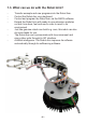
1. PRODUCT DESCRIPTION ROBOT ARM This big metal Robot Arm is ideally suited for school and educational projects to learn the basics of electronics, mechanics and programming. The ROBOT ARM is controlled by a powerful ATMEGA64 microcontroller that is programmable via Open Source Tools in C. The user can upload his own programs simply and easily via the supplied USB interface and the Uploader software.
1.3. What can we do with the Robot Arm? - Transfer example and new programs into the Robot Arm. Control the Robot Arm via a keyboard Control and program the Robot Arm via the RACS software. Extend the Robot Arm with ready-to-use extension modules so that it can hear, feel and see in order to react to its environment Just like genuine robots can build e.g. cars, this robot can also do some tasks for you. The Robot Arm can communicate with its environment and many other units through its I2C interface.
2. Required tools Needle-nose pliers Sidecutter Screwdriver set Screwdriver Included Selftapping screws (Parker) Selftapping screws behave like wood screws i.e. they cut a thread into the material in a rotating motion that functions like a nut. To this end, this type of screw has a larger thread and a sharper tip as a normal screw. Selftapping screws have a cutout at the top that makes it easier to drill into the material.
3. PART LIST Servomotor O 6 pcs. maxi Servo-Disc Plastic O 3 pcs O 1 pc. O 3 pcs. Spacer M3x6 O 4 pcs Keyboard O 1 pc. O 1 pc. O 1 pc. Metall-Disc with axis Servo-Hebel Big USB lead CD Servo-Disc Metall Big A Servo-Disc Metall Big B O 1 pc. O 1 pc. Servoholder Mounting arm Montage Winkel O 1 pc. O 1 pc. O 1 pc. Spacer M3x16 Spacer M3x40 O 2 pcs. O 4 pcs. -6- Spiral O 1 pc.
Finger Part B Finger Part A O 1 pc. O 1 pc. Servo bottom plate Servo coupling rod M3 - M4 O 1 pc. Robot Arm base Fingerspitze O 4 pcs. Servo coupling rod M2 - M3 O 2 pcs. O 2 pcs. PCB Programming lead Program adaptor O 1 pc. Servo extension lead O 1 pc. Keyboard lead O 1 pc. O 1 pc. Kuppelstange O Servos-Hebel Klein O 2 pcs. O 1 pc. Round-head screw Selftapping screw M3x20 M3.2x6 O 1 pc. 5 pcs. Round-head screw M3x6 O 1 pc. O 9 pcs. O 4 pcs.
4. Mounting instructions for mechanical parts 4.1. Mounting parts in this construction kit Bottom plate Arm Gripper Round-head screw M3x8 O 8 pcs Spacer M3x16 O 2 pcs. Option Abstandsbolzen als Kabelführung von Servokabels Selftapping screw M3.2x8 O 2 pcs.
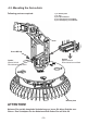
4.2. Mounting the Servo-Arm: Following parts are required: 1 pc. Bottom plate 1 pc. Arm 2 pcs. Spacer M3x16 4 pcs. Round-head screw M3x8 2 pcs. Selftrapping screw M3.2x8 Arm Screw M3.2x8 Option Spacer M3x16 Round-head screw M3x8 Option Spacer M3x16 Round-head screw M3x8 Bottom plate ATTENTION! Nehmen Sie erst die komplette Verkabelung vor, bevor Sie diese Schritte ausführen. Den Schaltplan für den Kabelanschluß finden Sie auf Seite 20.
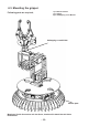
4.3. Mounting the gripper: 1 pc. Bottom and Arm 1 pc. Gripper 2 pcs. Selftapping screw M3.2x8 Following parts are required; Selftapping screw M3.
READY ! Selbstzapffendeschraube M2.
Terminal assignment on the main PCB Connect the servos via the servo extension leads and use the spiral to run the wires properly.
5. Starting the Robot 1. 2. 3. Start by assembling the mechanical and electronic modules of the Robot Arm by reading the mounting instructions. If necessary, connect the 9V mains adaptor (7- to 12 V max.). Switch the robot on with the main On/Off switch. Voltage supply Mains adaptor There are 2 options to power the robot. The easiest solution is to connect a mains adaptor with an output voltage of 7-12V / 2 Amps to the DC 9V input. This way, the voltage is connected to the INPUT of the voltage regulator.
6. Software Installation Let’s do the software installation now. A properly installed software is of paramount importance for all following chapters. As you need administrator rights, you have to log into your system as an administrator! We recommend to read the whole chapter thoroughly first and then start with the installation step by step.
If the safety settings of your web browser don’t allow a direct installation from the CD-ROM, you have to copy the files first into a directory on your hard disc and start the installation from there. For more details please refer to the software page in the CD menu. Alternatively, you can also switch to the CD drive through a file manager and install the software from the CD.
If you use Windows Vista or Windows 7, you must install the latest version of WinAVR! It should also work perfectly with Windows 2K and XP. If not, you can try one of the older versions that are also on the CD (before you make a new installation of WinAVR, you have to uninstall the existing version first!). Officially Win x64 is not yet supported but the CD contains a patch for Win x64 systems if a problem arises. You will find more information on the software page of the CD menu.
If a path is displayed, a version is already installed. So just enter: > avr-gcc --version and look at the output. If the displayed version is smaller than 3.4.6, you have to uninstall in any case this obsolete version. If the version number lies between 3.4.6 and 4.1.0, you can try to compile programs (see following chapter). If it fails, you have to install the new tools. We will install hereafter the currently most updated version 4.1.1 (status March 2007) together with some important patches.
Attention: You should have enough free disk space on your hard disk! Temporarily more than 400Mb are required. Over 300Mb can be erased after the installation but during the installation, you need all the space. Many of the following installation steps require ROOT RIGHTS, so please log in with “su” as root or execute the critical commands with “sudo” or something similiar as you have to do it in Ubuntu e.g. (the installation script, mkdir in /usr/ local directories and make install require root rights).
Automatic Installation Script Once you have made the script executable via chmod, you can start immediately: > cd ~/Robot Arm > chmod -x avrgcc_build_and_install.sh > ./avrgcc_build_and_install.sh Answer “y” to the question if you want to install with this configuration or not. PLEASE NOTE: The compilation and installation will take some time depending on the computing power of your system (e.g about 15 min. on a 2GHz Core Duo Notebook. Slower systems will need longer).
If you don’t know exactly what has gone wrong, please save all command line outputs in a file and contact the technical support. Please join always as much information as possible. This makes it easier to help you. GCC for AVR The GCC is patched, compiled and installed a bit like the binutils: > cd ~/Robot Arm> bunzip2 -c gcc-4.1.1.tar.bz2 | tar xf > cd gcc-4.1.1 > patch -p0 < ../gcc-patch-0b-constants.diff > patch -p0 < ../gcc-patch-attribute_alias.diff > patch -p0 < ../gcc-patch-bug25672.
Important: at –build=`./config.guess` make sure to put a backtick ` (à <-- the grave accent on the a! ) and not a normal apostrophy or quotation marks as this wouldn’t work. Set the Path You must make sure now that the directory /usr/local/avr/bin is registered in the path variable otherwise it will be impossible to retrieve the avr-gcc from the console or from the makefiles.
Manual Installation If you prefer to install the compiler manually or the installation via th script failed, you can follow the instructions below. The description is based on following article: http://www.nongnu.org/avr-libc/user-manual/install_tools.html that is also included on the CD in PDF format in the AVR Libc documentation: :\Software\Documentation\avr-libc-user-manual-1.4.5.pdf Our description here is much shorter but includes a few important patches.
Binutils for AVR Now you must unpack the sourcecode of the binutils and add a few patches. We suppose in our example that you have copied everything into the home directory ~/Robot Arm: > cd ~/Robot Arm > bunzip2 -c binutils-2.17.tar.bz2 | tar xf > cd binutils-2.17 > patch -p0 < ../binutils-patch-aa.diff > patch -p0 < ../binutils-patch-atmega256x.diff > patch -p0 < ../binutils-patch-coff-avr.diff > patch -p0 < ../binutils-patch-newdevices.diff > patch -p0 < ../binutils-patch-avr-size.
Windows The JRE 1.6 for Windows is in following folder: :\Software\Java\JRE6\Windows\ Under Windows the installation of Java is very simple. You just have to start the setup and follow the instructions on the screen - that’s it. You can skip the next paragraph. Linux Under Linux the installation doesn’t present any major problems although some distributions require some manual work. In the folder: :\Software\Java\JRE6\ you will find the JRE1.6 as an RPM (SuSE, RedHat etc.
You can check if Java has been correctly installed by entering the command “java-version” in a console. The output should be approximately as follows: java version “1.6.0” Java(TM) SE Runtime Environment (build 1.6.0-b105) Java HotSpot(TM) Client VM (build 1.6.0-b105, mixed mode, sharing) If the output is totally different, you have either installed the wrong version or there is another Java VM installed in your system.
The long -D option is necessary to enable the JVM to find all used libraries. Windows doesn’t require this and you can just start with the .exe file. Linux requires the shell script ”RobotLoader. sh“. It might be necessary to make the script executable (chmod -x ./RobotLoader.sh). After that you can start it in a console with “./RobotLoader.sh“. It is advisable to create a shortcut on the desktop or in the start menu to make the start of the Robot Loader more convenient.
7. Programmer and Loader To load a HEX Robot Arm program from the PC into the Robot Arm, we will use the USB programming adaptor and our RobotLoader software. The loose USB port adaptor transmitter/receiver (transceiver) included in the package must be connected on one side to a USB port of the computer and on the other side to the Prog/UART port of the Robot Arm PCB. The program upload into the Robot Arm erases automatically the previously existing program.
7.1. Robot Loader As said, the RobotLoader has been developed to upload easily new programs into the Robot Arm and into all our robots (provided that they contain a compatible bootloader). RobotLoader If the voltage drops below < 4.4 V, a warning is displayed. The maximum voltage that the RobotLoader is able to measure, is 5.1 V! Weiterhin sind ein paar nützliche Zusatzfunktionen integriert, wie z.B. ein einfaches Terminalprogramm.
7.2. Connection of the USB interface – Windows Linux users can skip to the next section! There are several options to install the USB interface, the easiest being the installation of the driver BEFORE the first connection of the hardware. The CD contains an installation program for the driver. For 32 and 64 Bit Windows 7, XP, Vista, Server 2003 and 2000 systems: :\Software\USB_DRIVER\Win2k_XP\CDM_Setup.exe For old Win98SE/Me systems, such a handy program does unfortunately not exist.
If you are in this situation, a dialogue appears (under Windows) to install the new driver. You have to indicate the path to the system where it can find the driver. Under Windows 2k/XP you need to select first the manual installation and not to look for a web service. On our CD the driver is in the above mentioned directories.
OR alternatively: Start --> Settings --> Control panel --> Performance and Maintenance --> System --> Hardware --> Device manager and check there in the tree view under “Connections (COM and LPT)” if you find a “USB-Serial Port (COMX)” - the X replacing the port number, or look under “USB serial bus controller“ for a “USB Serial Converter“ ! If you wish to uninstall the driver some day If ever you wish to uninstall the driver (no, not now - this is just a hint if you need this some day): If you have used th
7.3. Connection of the USB Interface – Linux Windows users can skip this section! Linux systems with kernel 2.4.20 or higher already include the required driver (at least for the compatible previous model FT232BM of the chip on our USB interface, the FT232R). The hardware is automatically recognized and you have nothing else to do. In case of a problem, you can get Linux drivers (and support and maybe also newer drivers) directly from FTDI: http://www.ftdichip.
7.4. Testing the USB Interface and starting the RobotLoader The next step is a test of the program upload via the USB interface. Connect the USB interface to the PC (always connect the PC first!) and the other end of the 10-pin ribbon cable to the “PROG/UART” connector on the Robot Arm. (Robot Arm MUST BE SWITCHED OFF!) The 10-pin ribbon cable is mechanically protected against polarity inversion. As long as it is not forced, it can’t be connected the wrong way round. Then start the RobotLoader.
7.5. Open a port – Linux Linux handles the USB serial adaptor like a normal comport. The installation of the D2XX driver from FTDI would not be as simple as that under Linux and the normal virtual comport (VCP) drivers are included anyway in the current Linux kernels. It works almost the same as under Windows.
7.6. SELFTEST The yellow voltage LED lights up when the Robot Arm is switched on. The status LED goes off when a HEX file is uploaded. As soon as a program is started, the status LED lights up in red. In the robot status “Ready”, the same LED lights up in green. If this worked, you can execute a small selftest program to test the functioning of all robot systems.
Please select the “RobotArm_Selftest.hex“ file in the list and click on the “Upload!“ button on the top right just below the progress bar. The program will now be transferred into the MEGA64 processor on the Robot Arm. This should not take more than a few seconds (max. 5 seconds for the selftest program). Switch to the tab (at the bottom of the window!) “Terminal“! Alternatively you can also switch to terminal via the menu item “View”. Now you can execute the selftest and the calibration of the Robot Arm.
7.7. Calibration Start the calibration program to calibrate the robot. To this end, please click on the button “Add” at the bottom of the RobotLoader window and select the file RobotArmExamples [MINI], „Example_11_Selftest\ RobotArm_Selftest.hex“ in the example directory. This file contains the selftest program in hexadecimal format. The just selected file will appear subsequently in the list (see screenshot). Select C (C - Calibrate) in the calibration program to start calibration.
Calibration position Servo 1 Finger Servo 2 Rotate wrist Servo 3 Bend wrist Servo 4 Elbow Servo 5 Shoulder Servo 6 Base (azimuth) - 38 -
7.8. Keyboard Test The set is supplied with a keyboard that can be connected to the Robot Arm. It is a good option for simple demonstrations and allows us to practice the control of a robot arm via a keyboard. The keyboard is fitted with 6 control keys and 4 special keys for later extensions. If we want to test the Robot Arm via the keyboard, we need to transfer the appropriate hex program into the robot’s microprocessor.
8.0. RACS Software RACS (Robot Arm Control Software) is the easiest way to control and program the Robot Arm. Programming via the RACS method requires the RobotLoader software and the USB programming adaptor. Prior to using the robot, you need to upload the HEX software RAC-PRO.hex into the Flash memory of the processor. Connect the programming/control lead to the USB port on your computer and start the Loader software. Following user interface is displayed: Fig.
In step 3 click on the button “Upload” to import the file. If you want to operate the Robot Arm, you have to disconnect the RobotLoader in Step 1 by clicking on the button “Close”. If you close the program, the connection is automatically interrupted. Please make sure that there is no connection between the Loader software and the Robot Arm, otherwise the robot can’t be controlled via the RACS software. 7.1. RACS Instruction Manual The Robot Arm can be controlled very easily via the RACS software.
7.2. RACS - Connection 1. Double-click on the Robot Arm Control Software to start it, following interface is displayed: Fig. 2 2. In the dropdown menu are listed all serial interfaces Fig. 3 3. Plug in the USB programmer 4. Click on Update button. When you look again that the dropdown menu, you will see an additional interface. This interface has been initialized by plugging in the USB programmer.
5. Select the new interface Fig. 4 6. Enable the checkbox “Connect” Fig. 5 7. Enable the checkbox “servo power” Fig. 6 8. Move the slider to control the servos. If an error occured during the establishment of the connection, following window appears. The connections must be established again (repeat steps 2-6 and check the interface). Fig.
7.3.
8.0. Programming the Robot Arm Now we are gradually coming to the programming of the robot. Setting up the source text editor First of all, we need to set up a little development environment. The so-called “source text” (also called “sourcecode”) for our C program must be fed into our computer one way or the other! To this end, we will definitely not use programs like OpenOffice or Word! As this might not be obvious for everybody, we stress it here explicitly.
See on page 47 “Open and compile an example project” how you can open an example project! If you have opened an example project, it should look a bit like this on the PN2 screen: “Robot ArmExamples.ppg“ file. This is a project group for PN2 that uploads all example programs plus the Robot Arm Library into the project list (“Projects“) .
Open and compile an example project Let’s test now if everything runs properly and open the example projects: Select in the “File“ menu the item “Open Project(s)“. A normal file section dialogue appears. Search the folder “Robot Arm_Examples [MINI]\“ in the folder into which you have saved the example programs. Open the “Robot ArmExamples.ppg“ file. This is a project group for PN2 that uploads all example programs as well as the Robot Arm Library into the project list (“Projects“).
We will explan this in detail a bit further down (there is also a version of this program WITHOUT comments so that you can see how short the program is in fact. The comments inflate it a lot but are necessary for the understanding. The uncommented version is also useful to copy the code in your own programs!). First of all we just want to test if the compilation of programs works properly. In the Tools menu on top both freshly installed menu items (see fig.
After the activation of the menu item MAKE ALL, following output should display (below in a considerably shortened version! Some lines may look of course a bit different): > “make.exe” all -------- begin -------- avr-gcc (WinAVR 20100110) 4.3.3 Copyright (C) 2008 Free Software Foundation, Inc. This is free software; see the source for copying conditions. There is NO warranty; not even for MERCHANTABILITY or FITNESS FOR A PARTICULAR PURPOSE.
The “Process Exit Code: 0“ at the end is most important. It means that no error occurred during compilation. If another code appears there, the sourcecode contains an error that must be corrected before it will work. In this case, the compiler will output various error messages that give some more information.
This means that the example programs above leave 60414 bytes of free space. The relatively short example program Example_01_Leds.c is only so big because the Robot ArmBaseLibrary is included! So, don’t worry, there is enough space for your programs and so small programs usually don’t need so much memory space. The function library on its own needs several kb of Flash memory but makes your job much easier and therefore your own programs will generally be quite small compared to the Robot ArmBaseLibrary.
As a conclusion We hope that our robots have guided you on your way into the world of robots. We share the conviction of our Japanese friends that robots will become the next technological revolution after computers and mobile phones. This revolution will trigger new economical impulses. Unfortunately Japan, other Far East countries and also the USA have largely overtaken Europe in this field.
APPENDIX - 53 -
A B C D 1N4148 D3 VCC C8 100n C6 100n L2 10uH VCC R4 10k C7 10n 1 RST RESET SS SCK MOSI MISO bep servo1 servo2 servo3 servo4 servo5 servo6 INT6 INT7 PDI PDO current1 current2 current3 current4 current5 current6 UBAT EXT_ADC 19 18 1 20 10 11 12 13 14 15 16 17 2 3 4 5 6 7 8 9 64 62 63 61 60 59 58 57 56 55 54 VCC U2 (RD) PG1 (WR) PG0 (A8) PC0 (A9) PC1 (A10) PC2 (A11) PC3 (A12) PC4 (A13) PC5 (A14) PC6 (A15) PC7 (AD0) PA0 (AD1) PA1 (AD2) PA2 (AD3) PA3 (AD4) PA4 (AD5) PA5 (AD6) PA6 (
- 55 - A B C 1 Power DC 12V R1 390 1N5400 D1 LED1 0.1u C1 +UB C2 1000u/35V 1 VIN GND 2 C14 0.1u 3 5 VCC ON/OFF 2 C15 0.1u VOUT FDB LM2576-5 TAB 6 D 1 2 4 C16 0.1u U1 D2 1N5822 22u L1 C3 1000u/16V 3 3 C4 0.1u Date: File: A4 Size Title R3 100k R2 100k VCC C5 0.1u UBAT 4 Sheet of 7-Jun-2010 Drawn By: F:\硬件原理\mini robot ARM\mini robot.ddb Number 2700mah size AA 1.2V Ni-MH 4 pcs Battery 4.8V SW1 4 Revision A B C D B.
- 56 - A B C D 1 RESET TXD1 PDI SCK RESET 1 prog/uart 1 3 5 7 9 J2 ISP 1 3 5 J1 2 4 6 8 10 2 4 6 VCC RXD1 PDO VCC VCC VCC SS MOSI PD4 PD6 RESET RESET INT6 2 2 J3 SPI 1 3 5 7 9 11 13 J4 IICBUS 1 3 5 7 9 11 13 2 4 6 8 10 12 14 2 4 6 8 10 12 14 VCC SCK MISO PD5 PD7 INT6 INT7 SCL SDA +UB PA0 PA1 PA2 PA3 0.
- 57 - A B C D PA6 PA4 1 1 1N4148 D10 1N4148 SERVO5_DWN PA1 1N4148 D12 1N4148 D11 PA0 D9 SSERVO5_UP 1N4148 1N4148 PA1 D3 D4 PA0 D2 SERVO1_DWN SSERVO1_UP 1N4148 D1 1N4148 2 2 PA7 PA6 PA5 PA4 SERVO6_DWN SSERVO6_UP SERVO2_DWN SSERVO2_UP PA3 PA2 PA3 PA2 2 4 6 8 ext key pad 1 3 5 7 J1 PA3 PA2 PA1 PA0 PA7 PA5 D5 1N4148 D14 1N4148 D13 1N4148 D6 1N4148 3 3 Date: File: A4 Size Title TANK_BCK TANK_FNT SERVO3_DWN SSERVO3_UP PA1 PA0 PA1 PA0 D8 1N414
E.