
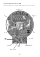
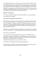
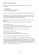
Instructions Circuit Diagram

- 13 -
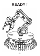
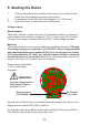
5. Starting the Robot
1. Start by assembling the mechanical and electronic modules of the
Robot Arm by reading the mounting instructions.
2. If necessary, connect the 9V mains adaptor (7- to 12 V max.).
3. Switch the robot on with the main On/Off switch.
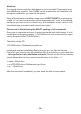
Voltage supply
Mains adaptor
There are 2 options to power the robot. The easiest solution is to connect a
mains adaptor with an output voltage of 7-12V / 2 Amps to the DC 9V input.
This way, the voltage is connected to the INPUT of the voltage regulator.
Batteries
The second solution is to connect a battery to the battery terminal. This way,
the battery voltage is connected to the OUTPUT of the voltage regulator
and should therefore never exceed 5.5V!! If you use 4 pieces of normal
1.5V mono batteries (‘D’ cells), you should connect a diode in series (in
forward direction) to the positive wire. Even more appropriate would be 4
pieces of the large 1.2V mono D size accumulators.
If the voltage drops below
< 4.4 V, a warning is
displayed.
As soon as the Robot Arm is connected to a power supply, the servos move
slightly and the yellow LED (LED1) lights up.
So, the start was not as difcult as that and it looks as if the job is nished
now. But the real hard work does only start now.....!
DC Terminal
7 to 12 Volt
Battery terminal
5,5 Volt MAX !
WARNING!
The max. voltage that the
RobotLoader is able to
measure is 5.1 V!