JM3-MARVIN-01 Developed by JM³ Engineering User Manual Marvin IoT Robot (c) 2015-2017 AREXX Engineering und JM³ Engineering www.arexx.com The latest updates are available at jm3-engineering.com! AREXX Engineering & JM³ Engineering Version: 1.2.
Imprint © 2016-2017 AREXX Engineering Nevistraat 16 8013 RS Zwolle The Netherlands Tel.: +31 (0) 38 454 2028 Fax.: +31 (0) 38 452 4482 This manual is protected by the laws of Copyright. It is forbidden to copy all or part of the contents without prior written authorization! Product specifications and delivery contents are subject to changes. The manual is subject to changes without prior notice. You can find free updates of this manual on http://www.arexx.
Precautionary Notes • Check the polarity of the voltage. • Always keep the electronic equipment dry. In the case of moisture immediately remove the batteries or the power supply to power down the device. This precaution is needed to keep it from short circuiting. Drying is needed to avoid corrosion. • Remove batteries before long-term storage respectively remove the power supply if the robot is not to be used for some time.
Laser Security Notes Proximity Sensor VL6180X 80/87 DocID026171 Rev 7 The VL6180X Proximitiy Sensor is equipped with a laser source and a laser control module. The output power of the laser light source is designed and limited to always comply with the safety limits according for Class 1 Laser sources. This also includes singular accidents according to IEC 60 825-1:2007.
Contents 1 Introduction 2 Manual 2.1 Marvin robot hardware . . . . . . . . . . . . . . . . . . 2.2 Marvin robot equipment and accessories . . . . . . . . . 2.2.1 Features . . . . . . . . . . . . . . . . . . . . . 2.2.2 Detection range of the proximity-sensors . . . . 2.2.3 Installation of additional proximity sensors (rear) 2.3 Commissioning . . . . . . . . . . . . . . . . . . . . . . 2.3.1 Documentation and software . . . . . . . . . . 2.3.2 iRP WebIDE . . . . . . . . . . . . . . . . . . . 2.3.
. . . . . . . . . . . . . . . . . . . . . . . . . . . . . . . . . . . . . . . . . . . . . . . . . . . . . . . . . . . . . . . . . . . . . . . . . . . . . . . . . . . . . . . . . . . . . . . . . . . . . . . . . . . . . . . . . . . . . . . . . . . . . . . . . . . . . . . . . . . . . . . . . . . . . . . . . . . . . . . . . . . . . . . . 33 33 33 33 Technical data 6.1 Dimensions and weight . . . . . . . 6.2 Power supply and power requirement 6.
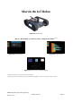
Marvin the IoT Robot Figure 0.1 Marvin Robot Marvin - iRP WebIDE - for browsers on PC, Notebook and Tablet *1) *2) Figure 0.2 Welcome-Screen Figure 0.3 Program-Screen Figure 0.4 Remote Control and Status Display *1) Apple iPAD or MacBook can store programs only on the robot, not on local disk. *2) Firefox, Google Chrome (PC/Notebook/Samsung Galaxy Tab A) and Safari (iPad Pro/MacBook Air) are tested - Internet Explorer or Edge are not supported. AREXX Engineering & JM³ Engineering Version: 1.2.
1 Introduction The JM3 IoT robot, called Marvin, impresses with its equipment and performance. Main components are the TIVA TM C microcontroller with ARM Cortex-M4F and 512KByte Flash, 256KByte SRAM, 6KB EEPROM, and the CC3100 WI-FI® Network Controller that meet the standards 802.11 b/g/n with up to 16Mbps data rate, multi-connection, TCP and UDP. Optimal adapted PCB antenna, infrastructure & ad-hoc mode with a range >25m under normal conditions.
Accessories (not included) • AA batteries (Ultra Power) or rechargeable batteries NiMH e.g. Ansmann HR06 Typ 2700 • Charger MW3310HC / 1 A Charging current setting • USB-Kabel (Micro-B / Type A) Sensor module extensions: Extension Board (Arduino compatible, iRP programable) • Interface with socket prepared for barometer or GPS module • For your own hardware extensions AREXX Engineering & JM³ Engineering Version: 1.2.
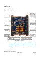
2 Manual 2.1 Marvin robot hardware Arduino Ext. Shield header Proxi-Sensors Power Supply 5.0 V und 3.3 V Micro-SD Card TivaC 1294 WiFi Subsystem USB Interface 9D Sensor Odometer Battery-Holder 6 x AA Proxi-Sensors (optional) Motor-Driver Button Main-Switch Charge-Plug (for rechargable batteries) Figure 2.1 Marvin robot hardware Hint: The best thing to handle the Marvin robot is to grab it on the battery compartment or on the chains.
2.2 Marvin robot equipment and accessories 2.2.1 Features The IoT robot provides many new possibilities: • TIVA TM C- mikro controller ARM Cortex-M4F Core (Floating Point) with 512KByte Flash, 256KByte SRAM, 6KB EEPROM, CC3100 WI-FI® 802.11 b/g/n – up to 16 Mbps, optimized PCB antenna, Infrastructur- and Ad-Hoc Mode, Flash-ROM 8Mbit • Virtual display on PC or Tablet-PC. • 3x Proximity / Ambient Light Sensor (Time of Flight) in front at the center – right and left.
2.2.2 Detection range of the proximity-sensors The sensors have a detection range (FoV) of 25° and a range of approx. 30 cm. Distances below 10 cm are displayed as zero. This ensures that the robot can avoid the obstacles without having to go backwards. The two external sensors are twisted at +15° or -15° to the robot zero axis to achieve a wider angle of detection. The representation of the resulting detection range shows a slight overlap of the individual sensors.
2.2.3 Installation of additional proximity sensors (rear) The sensors have a pitch of 1.27mm - half as much as usual. Therefore you should have a soldering iron with a fine tip and a power of approx. 50 W power. Pay attention to the vertical position of the sensors and do not make them stand out. It is recommended to first solder only one pin, then align the sensor and then solder all other pins. The details on activating the sensors can be found in subsection 2.4.4.
Hint: In the delivery condition, the robot is set to the WiFi AdHoc mode so that it can communicate directly with a PC with a Wifi interface (Notebook, T-Tablet, etc.). There are a variety of micro SD cards that have different characteristics and are available in Marvin may not work properly. SD-XC cards as well as SanDisk Ultra cards are generally not supported! Marvin software updates consist of the disk image with the iRP software. It also contains the appropriate firmware (hex-file).
2.3.3 iRP connection with PC/Tablet There are generally two different operating modes like the Marvin robot can be connected to the PC/Notebook via WiFi: • WiFi - Infrastructure mode: Connect Marvin to a network (WiFi router or access point) • WiFi - AdHoc Mode: here you can connect the Marvin directly to the notebook or tablet PC. – SSID: Marvin – IP: 192.168.1.
2.3.3.2 WiFi - Infrastruktur mode This mode must first be configured on the robot with the JM3 Robot Tool and logged on to the WiFi router. The Marvin supports DHCP and an IP address is automatically assigned. Hint: If necessary, change the firewall settings so that the Marvin robot can connect to the network! Please delete the browser cache if the iRP screen is not loaded properly! Here is the process for conversion to infrastructure mode: 1. Install the JM3 Robot Tool (installation - see chapter 4) 2.
5. Then open the browser and enter the IP address, for example: 192.168.1.120 You should see Figure 2.5 in the browser. That’s it - you can now familiarize yourself with the menu and load and run a first small program! 6. Load the sample program “running lights” 7. You should now see the status LED light up in different colors changing every 1 sec. Figure 2.5 Marvin WebIDE Welcomescreen AREXX Engineering & JM³ Engineering Version: 1.2.
2.3.4 Status LEDs To the status display of the robot (RGB-LED): • blue - normal function • Purple (blinking) - battery voltage low • Yellow - no SD card or function impairment, Notes on USB Interface.
2.3.5 System Display The key system status of the robot will be displayed in the “System Display”: The System Display shows the following elements (Figure 2.
2.4.1 RTC - set system time Setting the real time clock in the Marvin robot is initiated by pressing the “Set RTC” button. This completes the setting of the clock. Hint: The time now also continues with Marvin switched off for several months. The battery is recharged by switching on the robot. 2.4.2 Calibration of the 3D compass The procedure for calibrating the 3D compass is described below. The alignment to NWSE is automatically detected. A key must only be pressed or a command executed to start/stop.
Figure 2.8 Cardinal points and inclination vector • Repeat this for east, south and west, or a complete circle, if possible with intermediate values, which increases accuracy. Hint: Do not tilt the Marvin too quickly during calibration! 2.4.2.4 Step 4 - finalization of calibration After completing the procedure, close the calibration mode by clicking on the corresponding button “Finalize calibration” and check the result by aligning the robot with the corresponding and known direction of the sky. 2.4.
2.4.4 Proximity sensors activation The proximity sensors are activated or deactivated using the “conf” command. Details are in Table 2.1. For example, to activate the sensor in the center at the rear, enter the following in the command line: • conf add RM “Enter” and subsequently • conf save RM “Enter” This would have added the RM sensor (rear center) and saved the configuration permanently and the sensor is ready for operation. 2.4.
Hint: You can use the white Marvin Box for distance measurement! 2.4.5.2 Step 2 - process Now measure the respective minimum and maximum value of the detection range. • To do this, approach the obstacle (Marvin Box) from approx. 35 cm until the raw value is set to a value smaller than 255 in the display. • Find the exact point and write the raw value and the measured distance at the ruler.
2.5 Command line interface (CLI) Table 2.1 describes all commands with syntax that are available. AREXX Engineering & JM³ Engineering Version: 1.2.
Table 2.1 CLI Kommandos Command cal cmps cal gyro [--state] cal prox “sensor” “xNear” “mmNear” “xFar” “mmFar” conf “cmd” “sensor” light “on/off” setrtc “H_M_S_W_D_M_Y” wlan AP ssid “SSID” wlan AP passwd “passwd” wlan AP txpwr “pwr” wlan AP channel “ch” wlan AP MODE wlan STA addprofile “SSID” “passwd” wlan STA delprofile “ID” wlan STA txpwr “pwr” wlan STA ipcfg “DHCP” | “IP” “mask” “gw” “dns” wlan STA MODE wlan STA SCAN wlan DEFAULT wlan getIP version security updatekey “key.
3 Programming with iRP The graphical programming language Marvin - iRP is easy to learn and requires none previous knowledge of a programming language like C/C++. The various function blocks allow to create and execute programs on a logical level. 3.1 Introduction in iRP 3.1.1 Basic operation The general handling of a PC and browser is a prerequisite. Help-Menu (Light Bulb) Program-Menu (Worksheet) Tabs Link-Indicator Language-Menu Figure 3.
Start program Download Program Single-Step Delete / Trashcan Zoom Figure 3.2 Marvin WebIDE program buttons Hint: Other languages such as Spanish, Italian, French and Chinese (simplified) are supported. The online help is currently only available in German and English. 3.1.1.2 The light bulb symbol • Find the help function for the iRP blocks with brief explanations. • Notes on documentation and software. • General notes about the program (info) and you can get the start screen displayed again. 3.1.
3.1.1.5 Program Tab • Here you can edit your programs, e.g. Load, save, etc. . • You can also select the iRP mode (Beginner, Advanced, Expert) set to. 3.1.2 iRP help A help function to the iRP blocks is always easily accessible in the browser. • Click on the light bulb symbol (picture shown at the top left) or • Click on the question mark on the right side of the screen. The help sidebar scrolls to the currently used block automatically. (see Figure 3.3). Figure 3.3 The Marvin WebIDE Helpbrowser 3.1.
Figure 3.4 Mismatch of block types in iRP • Next to the “start button” is a “step button” (step by step execution of the program to the breakpoint), the download button, the zoom function and the trashcan - for blocks which are no longer required. 3.1.5 Program load or saved • Here you can load or save your programs. The location can be selected as usual. • It is also interesting to insert already developed parts of the program.
Figure 3.5 Beispiel für einen Compiler Fehler 3.1.7 Program code (source code) viewer For further debugging, it may be helpful to look at the source text - but this is rather something for advanced and experts. The selection is made by means of the program tab “source code” - in this case outputs as C++ source, C++ header and assembler are possible (Figure 3.6). Figure 3.6 Example for generated C++ code AREXX Engineering & JM³ Engineering Version: 1.2.
4 JM3 Robot-Tool 2.0 4.1 Linux • Copy the JM3 Robot Tool to a folder and run the program “launch_robotTool.sh”! Hint: Further details see install.txt • Click on the “Add Robot” icon - enter the name (freely selectable), the hostname and the USB port you are using and go to the next step. • Select the robot type, e.g. “Marvin”. The available USB port name can be looked up in the system configuration - the USB port is usually “/dev/ttyACM0”. Just type in the correct USB port e.g. “/dev/ttyACM0”.
with “SelectFile”. Select the hex-file you want to load into the micro controller. As a further step select the type, e.g. “Marvin”. • Click OK. • Select the robot and the program in the listed links. • Click “Upload program” (at the top of the toolbar) • Click “Save” (at the top of the toolbar), if you want to save the created robots and programs. 4.3 Windows 7 • Copy the JM3 Robot Tool to a folder and run the file “robottool.exe”.
4.4 Load your own programs created under C/C++ To upload a self-written program (hex-file) into the micro-controller you must have installed the JM3 RobotTool before you can continue (Figure 4.1). 4.4.1 Upload (Marvin application) • Start the JM3 Robot Tool It is assumed that the robot tool has already been prepared as described above. • Click on “Add File” to select the hex-file with the new program. The search simply goes over the path with “SelectFile”.
4.4.2 Upgrade Firmware (Bootloader) The firmware of the Marvin robot also allows to flash the bootloader itself to a later version. This requires the following steps. • Select the new boot loader (hex-file) as described above. • A click on “Upgrade Firmware” executes the update. Figure 4.1 The JM3 Robot-Tool AREXX Engineering & JM³ Engineering Version: 1.2.
4.5 Terminal window The terminal feature in the JM3 RobotTool allows serial data to be received and sent. It can also record data and save it to a file. Various settings are available “Settings”: • Connect to robot “Connect” allows data to be received. • Disconnect connection to robot “Disconnect”. • Send data to the robot “Right side - lower window” - commands can be entered here at any time. Please set line-ending characters to “LF” (line feed).
4.6 Firmware and iRP Micro SD-Card update In the following is a description of a software update process. Firmware update (all Operating Systems): The firmware update is performed with the JM3 Robot Tool. Details are described in chapter 4. • Connect to the PC/Notebook using a USB cable (Mirco-B / TypeA). • Start the JM3 Robot Tool and select the “Firmware.hex” file. • Turn on the Marvin robot and connect to the PC/Notebook. • Start it with a click on the “Upload icon”.
• Wait until the image has been copied completely. • Please “eject” the drive. 4.6.3 Micro SD-Card update (Mac OSX): The SD card image is executed with the command “dd”. • Insert the SD card with the USB adapter. • Open a terminal window. • Check the ID “/dev/diskN” of the SD card by running the command “sudo diskutil list”. • Note the ID of the SD card (it must have a size of approximately 2GBytes and contain exactly one Linux partition).
5 Option: C/C++ Software The C++ programming language has emerged from the C language and represents an extension and improvement of C. All in all the more modern language which gives a better readability of the code and a much better protection against side effects (e.g. enums / namespaces instead of often unclear #define instructions). Assembler and C program parts can be easily combined with C++ code.
5.1.1 Toolchain As compiler, the GCC for ARM (arm-none-eabi-gcc) must be used under Linux. Additionally, the following packages are required: make, newlib, arm-none-eabi-gcc and python. Any editor for the change of the source code can be used. The programming (s/w upload) is possible via the USB connection and the “JM3 Robot Tool”. Your program can be loaded quickly and effectively into the TIVA C. If you need full access to the microcontroller, you need a TIVA JTAG Interface (e.g.
6 Technical data 6.1 Dimensions and weight Width: 125 mm Length: 148 mm Height: 50 mm Weight: 195 g (without batteries) 6.2 Power supply and power requirement VCC Hint: = 8.4 V ± 5% => 6 AA cells The absolute maximum is bei 10.0 V !!! ICCAVR Hint: = 160mA +40.0 mA / -20.0 mA => without Arduino Extension Battery lifetime: ca. 5 h (Driving operation - engines at 50%) ca. 10 h while programming with iRP 6.
7 Schematic details 7.1 Arduino Extension Board Arduino Shields are supported by the Hardware. All common interfaces such as I2C, SPI, UART ADC and GPIOs or various timer outputs supoorting frequency or PWM generation e.g. for servo control. An input capture function is available for measuring frequencies and duty cycles. Table 7.
Figure 7.1 Marvin Arduino header - schematic AREXX Engineering & JM³ Engineering Version: 1.2.
7.2 Pin mapping TM4C129EKCPDT Table 7.
Pin Name 65 66 67 68 69 70 71 72 73 74 75 76 77 78 79 80 81 82 83 84 85 86 87 88 89 90 91 92 93 94 95 96 HIB_N XOSC0 XOSC1 VBAT VDD RST_N PM7 PM6 PM5 PM4 PM3 PM2 PM1 PM0 VDD GND PL0 PL1 PL2 PL3 PL4 PL5 VDDC OSC0 OSC1 VDD PB2 PB3 PL7 PL6 PB0 PB1 Function Signal TSCCP1 TSCCP0 GPIO GPIO T3CCP1 T3CCP0 T2CCP1 T2CCP0 GPIO_T7 GPIO_T6 GPIO_T5 GPIO_T4 GPIO_T3 GPIO_T2 GPIO_T1 GPIO_T0 I2C2SDA I2C2SCL GPIO GPIO GPIO GPIO SDA_X SCL_X LED3_B LED2_G LED1_R WIFI_LED_GREEN GPIO GPIO GPIO GPIO GPIO GPIO HEAD_R HEA
7.3 PCB Print Figure 7.2 Marvin PCB Print AREXX Engineering & JM³ Engineering Version: 1.2.
List of Figures 0.1 Marvin Robot . . . . . . . . . . . . . . . . . . . . . . . . . . . . . . . . . . . . . . . . . . . 1 0.2 Welcome-Screen . . . . . . . . . . . . . . . . . . . . . . . . . . . . . . . . . . . . . . . . . 1 0.3 Program-Screen . . . . . . . . . . . . . . . . . . . . . . . . . . . . . . . . . . . . . . . . . . 1 0.4 Remote Control and Status Display . . . . . . . . . . . . . . . . . . . . . . . . . . . . . . . . 1 2.1 Marvin robot hardware . . . . . . . . . . . . . . . . . . . .