OPERATOR’S MANUAL is e th icle. v o t rem his veh o n Do from t ual man MANUAL NO.
A MESSAGE FROM THE PEOPLE WHO BUILT YOUR ARGO Thank you for selecting an ARGO amphibious, off-road utility vehicle! Ontario Drive & Gear Limited has been building ARGO vehicles since 1967. By listening carefully to our customers and responding to their needs, we have been constantly improving the ARGO and will continue to do so. Over thirty thousand ARGO vehicles have provided reliable service all over the world.
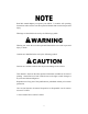
Read this manual before you operate your ARGO. It contains safe operating instructions and warns the user about potential hazards that can result in personal injury. Warnings are identified in the text by the following symbol: Warning text warns the user about potential hazards that can result in personal injury or death. Cautions are identified in the text by the following symbol: Caution text contains cautions that can prevent damage to the vehicle.
PREFACE This manual describes the controls, operation and basic maintenance procedures for all HDi, HD, AVENGER and FRONTIER models of the ARGO from date of printing. Please take the time to read this manual carefully, for your safety and that of others. By following these instructions, you will ensure extended, trouble free operation of your vehicle.
TABLE OF CONTENTS SECTION PAGE 1.0 GENERAL INFORMATION 1.1 AMPHIBIOUS OPERATION............................................................................................. 1.2 MAINTENANCE PROCEDURES.................................................................................... 1.3 WIND CHILL FACTOR ................................................................................................. 1.4 MODEL IDENTIFICATION...........................................................
TABLE OF CONTENTS SECTION PAGE 5.6.1 5.6.2 5.6.3 5.6.4 Entering Water..................................................................................................... 18 Driving Procedures in Water................................................................................ 18 Driving Out of Water........................................................................................... 19 Outboard Motor Bracket..................................................
TABLE OF CONTENTS SECTION PAGE 7.1.5 SPARK ARRESTER.................................................................................................. 30 7.2 DRIVE SYSTEM & TIRES..................................................................................................... 30 7.2.1 DRIVE BELT............................................................................................................. 30 Drive Belt Adjustment.......................................
TABLE OF CONTENTS SECTION PAGE 9.2 STORING THE VEHICLE.............................................................................................................. 49 Cleaning the Vehicle......................................................................................................................... 49 Drain the Fuel System......................................................................................................................
SECTION 1 GENERAL INFORMATION 1.1 AMPHIBIOUS OPERATION If the engine requires servicing, take the vehicle to an authorized engine service outlet. All models of the ARGO are amphibious and capable of traversing calm water. Special operating procedures and safety precautions must be observed before entering the water and during amphibious operation. Do not drive your vehicle into water until you have read Section 5.6 Amphibious Operation. 1.
SECTION 1 GENERAL INFORMATION 8x8 AVENGER 750 EFI (H) Carefully observe the maximum load capacity for your vehicle on land and in water as listed in the following: Engine: Kohler 748 cc (31 h.p.) V-twin 4 cycle, liquid cooled Transmission: 2 forward speeds, neutral and reverse Clutch: Variable speed torque converter Fuel Capacity: 27 Litre (5.9 Imp. Ga., 7.1 U.S Gal.) Steering/Brakes: Hydraulic Caliper, 10.
SECTION 1 GENERAL INFORMATION 6x6 650 HD (D) Engine: Briggs & Stratton Vanguard, 627 cc cooler cleaner running (23 h.p.) V-Twin, 4 cycle, air cooled Transmission: Forward, neutral and reverse with high/low range Clutch: Variable speed torque converter Fuel Capacity: 27 Litre (5.9 Imp. Ga., 7.1 U.S Gal.) Steering/Brakes: Hydraulic Caliper, 10.25" disc with holding brake system Drive Chains: Single RC-60 roller chain Electrical: 12 volt D.C.
SECTION 1 GENERAL INFORMATION 1.
SECTION 1 GENERAL INFORMATION 1.
SECTION 1 GENERAL INFORMATION 1.7 INFORMATION LABELS There are labels on all models which indicate operating hazards and provide special operating instructions. Information about the use of the holding brake system, the use of the vehicle in water, correct fueling procedures and placement of the floorpans has been provided on distinctive coloured labels fastened to the various locations on the Argo.
SECTION 2 GENERAL OPERATING INFORMATION 2.1 NEW VEHICLE “BREAK-IN” PROCEDURE 2.2 PRE-OPERATION CHECKS To obtain long term, trouble free service from your vehicle, observe the following break-in guidelines: Carefully follow the engine manufacturer’s recommended pre-operation/daily checks as well as the following: 1. Vary the speed of the vehicle for the first tank of fuel. Avoid full throttle operation during break-in period. 1.
SECTION 2 GENERAL OPERATING INFORMATION We recommend that you do not venture out in your Argo without being accompanied by an able-bodied person to assist you in case you encounter difficulty. If this is not possible, make sure that adequate communications equipment (eg. cell phone, two-way radio) with an independent power supply is on-board and communication lines are open at all times to call for help if necessary. Remember, a simple technical failure could leave you stranded.
SECTION 2 GENERAL OPERATING INFORMATION Land Operation tions, an ARGO can be driven for 7 to 12 hours on one tank of fuel. Verify your vehicle’s actual fuel consumption before attempting any long trips. Never travel in remote areas or set out on long trips without a full tank of fuel and adequate spare fuel stored in approved watertight fuel containers.
SECTION 2 GENERAL OPERATING INFORMATION Never use gasoline or other harsh solvents to clean the Argo body. All Camouflage material is especially vulnerable to damage and peeling if it comes into contact with gasoline. Take precautionary action when refueling to protect the body from any such occurances. 2.7 Instrument Cluster Beginning with 2009 model year, Argos are equipped with an LCD instrument cluster. Figure 2-1.
SECTION 3 OPERATING INSTRUCTIONS 3.1 BRAKES AND STEERING 3.2 EMERGENCY/PARKING BRAKE SYSTEM When in use, the emergency/parking brake system keeps the wheels locked in the full braking position. Do NOT oversteer. Avoid the tendency to push or pull harder on the steering system if the vehicle is not responding as expected. Once the steering brakes have been locked, pushing or pulling harder on the steering system will not increase the turning capacity of the vehicle.
SECTION 3 OPERATING INSTRUCTIONS 2. Turn the key switch to the "START" position, crank and start engine. 3. If the engine fails to start, repeat steps 1 and 2. If the engine does not start after two priming intervals, contact your Kohler Engine Service Dealer for further assistance. 3.7 STOPPING THE ENGINE Release the throttle twist grip. Let the engine speed return to idle and turn ignition switch to the “OFF” position. Always remove key from ignition switch when leaving the vehicle unattended.
SECTION 3 OPERATING INSTRUCTIONS 3.9 SELECTING AND CHANGING TRANSMISSION GEARS DO NOT CHANGE TRANSMISSION GEARS WHILE THE VEHICLE IS MOVING. To change gears, bring the vehicle to a complete stop, let the engine idle down completely, engage hand brake and move the shift lever to the selected gear. 3.9.1 Changing Transmission Gears - Avenger and Frontier Avenger and Frontier models are equipped with a four position transmission. The gearshift lever extends through the firewall and is moved in an "H" pattern.
SECTION 4 DRIVING PROCEDURES 4.3.1 Left Turn 4.1 DRIVING STRAIGHT AHEAD The Moto-Cross style steering bar is spring loaded to return to a centered position. (See Figure 4-1). At this location, no braking is applied to either of the calipers. It is at this position that the steering bar should be when driving straight ahead. Turn the throttle twist grip slowly until the clutch system engages and the vehicle moves forward. Do NOT oversteer.
SECTION 4 DRIVING PROCEDURES 4.5.2 HDi and HD Recommended Gear Selections 4.5 OPERATING INSTRUCTIONS - 750 HDi, 700 HD and 650 HD Trails and higher speed driving: Recommended gear selection HIGH range: In High range, the 750HDi and HD models will turn as tight as most ATV’s and UTV’s, which is ideal for trail riding. Compared to previous braked skid steer vehicles, these models will corner with minimal loss of speed or engine power.
SECTION 5 DRIVING PROCEDURES IN UNUSUAL CONDITIONS 5.1 REMOTE AREA USE 5.3 UPHILL OPERATION When traveling in remote areas or when traveling long distances, the following items are essential: • • • • • • • • • • • Never accelerate or brake suddenly while driving up or down a hill. Sudden acceleration or braking can cause the vehicle to roll over, causing serious personal injury or death.
SECTION 5 DRIVING PROCEDURES IN UNUSUAL CONDITIONS current. Avoid water operation under windy conditions. the possibility of rolling over. 5.5 SIDE SLOPE OPERATION 5. Do not use the Argo in water when equipped with tracks unless it is also equipped with an outboard motor. The tracks do not propel the Argo in water. Do not drive your vehicle across the side of a hill. Side slope operation greatly increases the risk of rolling the vehicle over sideways. 6.
SECTION 5 DRIVING PROCEDURES IN UNUSUAL CONDITIONS 3. Make sure that any cargo in the rear of the vehicle is evenly distributed. possible. With the wheels partially submerged but still in contact with the bottom, stop and check thoroughly for water entering the lower body. 4. Periodically inspect the outer bearing flange and gaskets of each axle (Figure 5-3) to ensure they are water tight. If there are signs of water leaking into the lower body, take corrective action before entering water again.
SECTION 5 DRIVING PROCEDURES IN UNUSUAL CONDITIONS 5.7.1 Use on Ice Covered Bodies of Water 5.6.3 Driving Out of Water When driving out of water, choose an area of the shore that is reasonably flat and free of rocks, stumps and other obstacles. Steer the vehicle so that both front wheels reach the shore at the same time. Accelerate slowly until the vehicle is out of the water. If vehicle is equipped with a ROPS system, refasten seatbelts.
SECTION 6 OIL, FILTER AND LUBRICATION INFORMATION 6.1 ENGINE OIL INFORMATION Do not run the engine if the oil level is above the FULL mark or below the ADD mark. Premature engine damage or total engine failure can occur when the oil level is not properly maintained. Detailed information on standard workshop and safety procedures and general installation practices is not included here.
SECTION 6 OIL, FILTER AND LUBRICATION INFORMATION 2. Level the vehicle so the oil will drain completely. 3. Place a suitable container under oil drain of engine and remove drain plug with a wrench: an 8 point 7/16" square socket for Briggs & Stratton engines or a 5/16" Allen socket for Kohler engines. Briggs & Stratton API Service Class SE, SF or SG There is limited space between the engine and power pack frame.
SECTION 6 OIL, FILTER AND LUBRICATION INFORMATION Figure 6-4b. HDi transmission. 6.2.3 Changing the Transmission Oil - Avenger and Frontier Figure 6-4a. 34-100 Transmission showing dipstick and drain plug locations Change the transmission oil after the first 20 hours of operation. After this, change the transmission oil every 100 operating hours. Remove firewall to access the drain plug located at the bottom of the transmission.
SECTION 6 OIL, FILTER AND LUBRICATION INFORMATION Overfilling may result in oil being forced out the breather hole that could contaminate the brake pads and lead to brake failure. For instructions to remove, clean and replace the air filter components, refer to the air cleaner section of the engine Owner’s Manual. Refilling the Transmission - HDi and HD 6.3.2 Fuel Filter - Avenger and HDi Install the drain plug. Remove the fill/vent plug located on the top of the transmission.
SECTION 6 OIL, FILTER AND LUBRICATION INFORMATION 6.4.3 Drive Chain Lubrication Your ARGO vehicle is equipped with roller chains to each axle. Lubricate the chains every 10 hours with Aerosol Chain Lube (ARGO Part No. 125-86), or more frequently in dirty or wet conditions. After every 100 hours of operation, or for extended periods of storage, remove all the drive chains from the vehicle and clean them thoroughly in a suitable solvent, i.e. degreaser. Figure 6-6b.Frontier fuel filter location.
SECTION 6 OIL, FILTER AND LUBRICATION INFORMATION First time operation: 1. Fill the reservoir with appropriate oil. 2. Remove the front floor pan, firewall, and rear floor pan. 3. Turn the key to run position, press and hold the override switch. You will hear the pump. 4. With the pump running watch below the drip tubes to see when the oil begins to drip. It may take close to 2 minutes of continuously holding the switch before the system is primed.
SECTION 6 OIL, FILTER AND LUBRICATION INFORMATION seals due to excessive grease pressure. Figure 6-10. and coupling connectors. Lubricate every 25 hours with a lithium based, NLGI #2 or 3 mineral oil based grease, (such as Shell Alvania #3). Wipe off excess. Figure 6-11. Output shaft grease fitting. Figure 6-10. Outer bearing flange. To promote regular maintenance of important Argo components, Ontario Drive & Gear has provided an access hole through each rim and hub for ease of bearing lubrication.
SECTION 6 OIL, FILTER AND LUBRICATION INFORMATION is taken out of service for any extended period. Dirt, dust and exposure to water will accelerate this servicing to less than 50 hour intervals. Only a small amount of grease is required. Figure 6-13. Inner axle flange grease nipple.
SECTION 7 MAINTENANCE INFORMATION as shown in Figure 7-1. If the fluid has dropped below the fill well, add distilled water until the cell is filled to correct level. DO NOT OVERFILL. 7.1 ELECTRICAL SYSTEM Detailed information on standard workshop and safety procedures and general installation practices is not included here. ODG assumes no responsibility or liability for PERSONAL INJURY or VEHICLE DAMAGE which results from any procedure performed, including those procedures outlined here.
SECTION 7 MAINTENANCE INFORMATION nificant decreases in performance. However, the design of many standard constant-voltage chargers may not permit it to recognize a battery with a voltage below 10.5 volts. If the OCV is less than 10.5 volts, take the following steps to get the OPTIMA battery to accept a charge: A Begin the process by connecting a good battery to the charger. B Connect the discharged OPTIMA battery (below 10.5 volts OCV) in a parallel connection with the good battery as shown.
SECTION 7 MAINTENANCE INFORMATION 7.1.3 ELECTRICAL SYSTEM FUSES replace the assembly with Part No. 607-171. All models of the ARGO are equipped with push-in type automotive fuses. The fuses protect the electrical circuits of the vehicle. They are located in the fuse block, inside the engine compartment, just in front of the steering system. Replace any blown fuses. Return your vehicle to an ARGO dealer for inspection of the electrical circuit if a fuse blows repeatedly. 9.
SECTION 7 MAINTENANCE INFORMATION • cracks, fraying or shredding is apparent • it becomes contaminated with oil or some other fluid Refer to the ARGO Parts Manual for correct drive belt part number. Drive Belt Adjustment To extend the life of the drive belt, the INVANCE driven clutch allows for some adjustment to reset the belt height if necessary. If belt wear causes the belt to start sitting below the sheaves at idle, adjustment can be made to bring the belt back up to flush or 1/10" above the sheaves. 1.
SECTION 7 MAINTENANCE INFORMATION 7.2.3 DRIVE CHAINS 2. Ease the belt over the edge of the fixed face on the driven clutch and at the same time, turn the inside, movable face clockwise. Roller chain “stretch” results from wear to the chain pins and bushings because of the loss of lubricant. Drive Belt alignment and tension are pre-set at the factory and are not adjustable. They are critical for proper operation of the drive system. Return the vehicle to an ARGO dealer if rapid belt wear occurs.
SECTION 7 MAINTENANCE INFORMATION Figure 7-5. Removal of the spring clip. To install the Drive Chains: 1. Position the drive chain over the slider block and around the drive sprockets. 2. Pull the ends of the chain together and insert the connecting link as shown in Figure 7-6 and 7-7. When connecting the RC50-2 chain, insert the inside plates before tapping the connecting link into position. Use a pair of modified 7R Vice Grips to hold the ends of the chain together while inserting the connecting link.
SECTION 7 MAINTENANCE INFORMATION bottom of the frame channels. Clamp it in this position with a Vice-Grip 10CR or similar plier as illustrated in Figure 7-10 and remove the drive chain. THE CAM ASSEMBLY IS PROGRESSING PROPERLY. CHECK FOR PROPER CHAIN TENSIONER OPERATION EVERY 10 HOURS OF VEHICLE OPERATION, WHEN THE DRIVE CHAINS ARE BEING LUBRICATED. Each step of the cam takes up about 3 inches of chain slack (see Fig. 7-8). 3.
SECTION 7 MAINTENANCE INFORMATION Figure 7-11. Hammering Slider Block into place. 7.2.5 IDLER CHAIN - Avenger & Frontier Figure 7-12. Measuring idler chain deflection To check the idler chain adjustment, push the slack side of the chain and measure the amount of chain deflection (Figure 7-12). Adjust the idler chain tension if deflection is more than 3mm (1/8"). HDi and HD do not employ idler chains in their design.
SECTION 7 MAINTENANCE INFORMATION To Remove the Idler Chains: can be ordered from your ARGO dealer (ARGO Part No. 65808) or refer to Appendix 1 for modification information. Loosen the power pack clamping nuts and adjusting bolts as shown in Figure 7-13 and proceed as follows: 3. Replace the outside plate and spring clip as shown in Figure 7-5. Note: Avenger and Frontier models are secured with two (2) cotter pins. Always use new cotter pins. 1.
SECTION 7 MAINTENANCE INFORMATION IMPORTANT It is ultimately the responsibility of the operator to determine a SAFE MAXIMUM load capacity in accordance with the driving terrain, conditions and vehicle specifications. 7.2.7 TIRE REPAIR AND REPLACEMENT Repair a flat tire by removing the tire completely from the rim. Proper tire changing equipment is necessary to remove and remount the tire. Your authorized ARGO dealer will have the necessary tools.
SECTION 7 MAINTENANCE INFORMATION If the brake fluid is below this level: 1. Add only fresh clean SILICONE - DOT 5 BRAKE FLUID (ARGO Part No. 126-19) to the correct level. Spilled brake fluid is environmentally damaging. Proper disposal is required. 2. Replace the cover on each master cylinder, making sure the rubber gaskets are properly seated before tightening the cover screws. Tighten snug by hand only. 7.3.4 HYDRAULIC BRAKE PAD INSPECTION Inspect the brake pads after every 25 hours of operation.
SECTION 7 MAINTENANCE INFORMATION Monitor the hand brake fluid on a regular basis. The master cylinder reservoir is translucent and the fluid level is visible to the eye without removing the cover. Ensure the level is to the “top” level mark. Figure 7-19a. Inspect all brake hoses and brake fittings at both hand brake and hydraulic calipers for any signs of brake fluid leaks.
SECTION 7 MAINTENANCE INFORMATION Argo to a full stop (unless required for safety reasons). Bringing the Argo to a full stop when the brakes are hot may cause the brake pad to imprint itself on the rotor. If this happens it will cause vibration and poor brake performance. 4. Repeat step 3 a total of 10 times. Do not wait between cycles to let brakes cool. Brake components will be extremely hot at this point. After the 10 cycles are complete, shut down the Argo and allow the brakes to cool down.
SECTION 7 MAINTENANCE INFORMATION The hand brake lever should be adjusted such that when pulled up firmly it is capable of holding the vehicle from rolling on a grade. It should also ensure a good braking response when applied to stop the vehicle during normal operation. 7.3.6 EMERGENCY/PARKING BRAKE ADJUSTMENT Adjusting the Emergency/Parking Brake (HDi and HD Models) There are 8 positions on the hand brake lever.
SECTION 7 MAINTENANCE INFORMATION Figure 7-21. Equalizer Flat Bar. Figure 7-23. Castle Nut. 4. Adjust the cable at the transmission until the cam levers are actually starting to pre-load the return springs and the cam lever actuation pin on the caliper, is centered in the "v-grove" of the cam. Figure 7-22. 6. Loosen the castle nut until it can be threaded by hand. 7. Using a 0.
SECTION 7 MAINTENANCE INFORMATION 15. The emergency/parking brake should be checked for proper adjustment every 25 hours. Note: Oil on the brake disc caused by improper chain oiling can permanently reduce the effectiveness of all brake systems. 850-98 Emergency/Parking Brake Kit is available for servicing of the emergency/parking brake pads on Avengers and Frontiers. The kit includes all necessary components and detailed servicing instructions.
SECTION 7 MAINTENANCE INFORMATION Type: Permanent type of anti-freeze; green coloured Mixed Ratio: 50% mixed Freezing Point: -35º C (-31º F) Coolant Capacity LH690/775 2 L (2.18 U.S. qt) If the vehicle is equipped with an enclosed cab of any sort, make sure there is plenty of ventilation to avoid exposure to exhaust and engine fumes. Engine exhaust contains carbon monoxide; an odourless, colourless toxic gas that will cause serious personal injury or death.
SECTION 7 MAINTENANCE INFORMATION 7.
SECTION 7 MAINTENANCE INFORMATION BEFORE EACH USE Check coolant level (Kohler engine) Check fan belt tension (Kohler engine) Check fuel level Check tire inflation Check twist grip throttle operation Check handlebar travel Check engine intake/exhaust for obstructions Check that drain plugs are in place Check engine oil level Change engine oil & oil filter - Kohler - Briggs & Stratton Check transmission oil level Change transmission oil Clean air pre-cleaner (Briggs only) Check clean/replace air filter Repla
SECTION 8 TROUBLE SHOOTING MALFUNCTION (SYMPTOM) PROBABLE CAUSE CORRECTIVE ACTION Electric starter inoperative 1. Loose electrical connections 1. Clean and re-tighten electrical connections 2. Battery charge low or dead 2. Recharge battery or replace as necessary 3. Faulty starter motor 3. Return the vehicle to an Argo dealer for servicing Engine turns over but will not 1. Engine is cold and choke is not 1.
SECTION 8 TROUBLE SHOOTING MALFUNCTION PROBABLE CAUSE (SYMPTOM) CORRECTIVE ACTION Severe vibration when vehicle 1. Engine loose on mounts 1. Take vehicle to an Argo dealer for is operated service. 2. Driver or driven clutch or engine 2. Same as above. defective 3. Axle bent 3. Remove and straighten or replace. 4. Wheel rim bent 4. Replace. 5. Worn or damaged drive belt 5. Replace. Clutch service may be required. Water leaks into lower body 1.
SECTION 9 CLEANING AND STORAGE 9.1 CLEANING THE VEHICLE Prepare the Battery for Storage Wash the vehicle body with a household detergent and rinse with water. Flush dirt out of the lower body by using a high pressure sprayer or garden hose after removing the drain plugs. After the bottom of the vehicle is dry, lubricate the drive chains with ARGO chain Lube. Make sure the drain plugs are replaced. Remove the battery from the vehicle. Clean it and charge it with a battery charger.
SECTION 10 POTENTIAL HAZARDS POTENTIAL HAZARD WHAT CAN HAPPEN HOW TO AVOID THE HAZARD Operating the Argo without reading and understanding the Operator’s Manual The risk of accident is greatly increased if the operator does not know how to operate the Argo properly in different situations and on different types of terrain. New or inexperienced operators should read and understand the Operator’s Manual. They should then regularly practice the operating techniques described in this Operator’s Manual.
SECTION 10 POTENTIAL HAZARDS POTENTIAL HAZARD WHAT CAN HAPPEN HOW TO AVOID THE HAZARD Operating or driving the Argo in water without the occupants wearing an approved personal flotation device (PFD). If you lose control of the Argo in water and it capsizes and sinks, the driver and passengers may be injured or drown. All occupants must wear an approved personal flotation device (PFD) or life jacket while travelling in water. Operating the Argo in water without taking along a paddle.
SECTION 10 POTENTIAL HAZARDS POTENTIAL HAZARD Operating the Argo with improper tires or with improper or uneven tire pressure. WHAT CAN HAPPEN Use of improper tires on the Argo, or operation of the Argo with improper or uneven tire pressure may cause loss of control increasing your risk of an accident. HOW TO AVOID THE HAZARD Always use the size and type tires specified in this Operator’s Manual for this Argo. Always maintain proper tire pressure as described in this Operator’s Manual.
SECTION 10 POTENTIAL HAZARDS POTENTIAL HAZARD WHAT CAN HAPPEN HOW TO AVOID THE HAZARD Side slope operation greatly increases the risk of Do not drive your vehicle across the side of a Improperly crossing hills or turning on hills. rolling the vehicle over sideways. hill. Prolonged side slope operation may cause engine damage. Observe the engine angle of operation limitations in Section 5.2. Stalling or rolling backwards while climbing a hill.
SECTION 11 ACCESSORY INFORMATION 11.1 GENERAL This section deals with accessories that have been specifically designed for the ARGO and can be purchased separately from your dealer. Special operating procedures and safety precautions must be observed before operating or using certain accessories. Only use track segments that show the Argo trademark. Other track systems may fail and damage axles, bearings and the final drive system.
SECTION 11 ACCESSORY INFORMATION Fig.11-4). If the extension studs are misaligned with the slots of the axle extension collar when tightened, adjust each stud as necessary by tightening them further (never by loosening them), until alignment allows for the extension collar to slide on easily (by hand), up against the axle hub. Torque to a minimum of 40 ft lbs. Once the extension studs are tightened and aligned correctly, they will not require re-tightening unless they are removed.
SECTION 11 ACCESSORY INFORMATION chain tensioning system and possibly, to other drive system components. Tires should be sized this way: a. With the tires still off the machine, inflate them all to 5.0 psi. b. Measure the circumference of each tire using a suitable tape measure, being sure to measure around the center-line of the tire. Figure 11-5. Write down the measurement on each tire. Figure 11-6. c. Install the tires as shown in the chart (Figure 11-7). Figure 11-5. Measuring the tire. Figure 11-7.
SECTION 11 ACCESSORY INFORMATION 9. Lay the two assembled tracks on the ground. Drive the vehicle forward onto the tracks until only two segments are in front of the tires. 10. Pull the remaining track around the rear tire and forward to the front of the vehicle. 11. Deflate the front and rear tires for easier installation of the final track pin. The gap between the adjoining segments should be between 0 to 1" for Avenger and Frontier models and 2 to 2-1/2" for all other models.
SECTION 11 ACCESSORY INFORMATION of the track pin from the vehicle side of the track. Once started, pull the pin out of the segment with Vise Grip. 11.3.7 Super Tracks Super Tracks provide the maximum “flotation” available for the Argo. They are very effective in deep snow, swamp and muskeg. 4. Pull the track off the top of the tires and drive the vehicle out of the tracks. Care must be used while traveling over uneven ground conditions.
SECTION 11 ACCESSORY INFORMATION 8. Deflate the front and rear (or all tires) for easier installation of the final track pin. 9. Join the two ends of the track and secure them in place with C-Clamps as shown in Figure 11-10, so that the holes of the hinge lacing line up. Figure 11-11. Measuring the gap of the mid tires - Avenger. Figure 11-10. Securing with C-clamps. 10. Insert the 825-56 Track Pin through one of the 108-23 washers and then through the hinge lacing.
SECTION 11 ACCESSORY INFORMATION Observe all operating precautions as outlined in 11.3.4 of this Accessory Section. 11.4 ICE CLEAT ASSEMBLY (Part Nos. 625-20, 82520 & 825-21) ARGO ice cleats are stamped steel cleats that bolt to the outer edges of the Rubber Tracks or Super Track segments to grip on hard pack snow and ice to improve traction and stopping. Figure 11-14. Measuring the gap of the mid tires - Frontier.
SECTION 11 ACCESSORY INFORMATION 11.6 ARGO STORAGE COVERS (Part Nos. 621-21; 821-20 & 821-40 ) The Argo storage covers prevent debris, rain water or snow from accumulating in the Argo. Secure the cover by pulling it down over the bumper and tying the cord tightly in place. A cord or tie strap through the side grommets and under the vehicle lower body securely holds the cover in place in windy conditions. Figure 11-16 Double Line.
SECTION 11 ACCESSORY INFORMATION 8. NEVER HOOK THE WIRE ROPE BACK ONTO ITSELF. Use a nylon sling. (Figure 11-18.) Hooking the wire rope onto itself can damage the rope (Figure 11-19). 11. Avoid continuous pulls from extreme angles as this will cause the wire rope to pile up at one end of the drum (Figure 11-21 & Figure 11-22). This can jam the wire rope in the winch causing damage to the wire rope or the winch itself. Figure 11-18. Correct hook-up. Figure 11-21. Incorrect positioning for continuous pulls.
SECTION 11 ACCESSORY INFORMATION 11.7.2 Tips for Extending the Life of Your Winch 1. 2. 3. Keep a tightly and evenly wound wire rope drum. Do not allow the wire rope to become loosely wound. A looselywound spool allows a wire rope under load to work its way down into the layers of wire rope on the drum. When this happens, the wire rope may become wedged within the body of the windings damaging the wire rope. To prevent this problem, keep the wire rope tightly and evenly wound on the drum at all times.
SECTION 11 ACCESSORY INFORMATION 11.13 CONVERTIBLE TOP (Part Nos. 649-51, 849-40, 849-45 & 849-51) 11.12 WINDSHIELD (Part Nos. 648-79 & 648-80) The windshield features an anodized aluminum frame with rubber mounted 24" high x 48" wide laminated safety glass. It mounts to the top of the dash area of any Argo model, folds down and secures in place over the hood and is required for the convertible top.
SECTION 11 ACCESSORY INFORMATION 11.14 ALTERNATOR ACCESSORY - For Avenger (Part No. 850-54) The externally mounted, belt driven, 40 amp alternator is recommended when electrical accessories such as a winch are added to the vehicle. There is a red charge indicator light installed in the dash, to the right of the ignition switch. If the red light comes on, the alternator is not sending a charge to the battery. This may simply be a result of low engine idle speed.
SECTION 11 ACCESSORY INFORMATION 11.18 ROLL OVER PROTECTIVE STRUCTURES (Part Nos. 648-47, 849-90-2 & 849-90-4) Seat belts must be properly adjusted and worn by all occupants at all times EXCEPT when operating in water. 6x6 vehicles equipped with 648-47 ROPS should not be used in water operation. Never carry more people in the vehicle than there are seat belts for. Articles must not be placed on top of the ROPS. Use caution when travelling on uneven ground; the ROPS reduces vehicle stability.
SECTION 11 ACCESSORY INFORMATION 11.20 ROLL BAR ACCESSORY (Part No. 648-15) The roll bar is designed for use on all Argo 6 x 6 models. The roll bar provides some roll over protection and lap belts for the driver and front seat passenger. This outlet is NOT designed to support nor should it be used as a cigarette lighter socket. 11.22 BRUSHGUARD ACCESSORY (Part Nos. 642-20 & 642-40) When the Roll Bar Kit is installed, ALWAYS wear seat belts when operating the vehicle on land.
APPENDIX 1 SPECIAL TOOLS 7R VICE GRIP MODIFICATION (Part No. 658-08) As detailed in Section 7, a pair of modified 7R Vice Grips is required to hold the ends of the drive chain together while inserting the connecting link. This tool can also be used to hold the ends of the idler chain together while inserting the connecting link. Grind the undercut and sides of the vice grip jaw to fit over 2 chain rollers. The undercut is approximately 1/4" radius as shown.
NOTES 69
NOTES 70
ARGO and CENTAUR New Vehicle Limited Warranty The warranty period is limited to 12 months for ARGO models and 12 months or 750 hours for CENTAUR models from the date of the original retail sale, with the following exceptions: Briggs & Stratton Engine – 24 months from the date of retail sale separately by the engine manufacturer’s service network. Kohler Engine – 36 months from the date of retail sale separately by the engine manufacturer’s service network.
ARGO RETAILER... Please complete this page at the time of sale to the new owner so your customer has all pertinent information that may be required. ARGO MODEL___________________________________________________ ARGO SERIAL NO.________________________________________________ ENGINE SERIAL NO.______________________________________________ TRANSMISSION SERIAL NO.