
Operator`s manual


54
SECTION 11
ACCESSORY INFORMATION
11.1 GENERAL
This section deals with accessories that have been specically
designed for the ARGO and can be purchased separately from
your dealer. Special operating procedures and safety precau-
tions must be observed before operating or using certain
accessories.
11.2 CARGO TIE DOWNS (Part No. 614-06)
Cargo tie downs are intended to assist in securing a load in
the rear compartment of any Argo. Use rope or elastic cords,
laced over the load and through the tie down rings, to hold
the load in place.
Never attempt to raise the vehicle by using the tie down
rings as lifting points.
Never exceed gross vehicle weight. Never exceed the
maximum rear compartment weight for 6-wheelers (65
kg/140 lbs.).
11.3 ARGO TRACK SYSTEMS (Standard Track - Part
Nos. 615-43 & 815-42K, Super Track - Part Nos. 625-43
& 825-42K & Rubber Track - Part Nos. 625-50 & 825-
50-1)
There are three different types of track systems available for
use with the Argo, the standard track system, the super track
system and the rubber track system. Standard tracks and super
tracks are similar in basic design and use the same pins and
lock collars to join the segments together. However, super
tracks and rubber tracks are wider than standard tracks and
require axle extensions and studs assembled to each wheel
hub.
The 625-50 & 825-50-1 Rubber Track Systems are NOT a
segmented track. This track is installed over the existing tires
and is hinged in one location only.
The track systems spread the weight of the vehicle over a
larger area than the tires, thereby reducing the ground pressure
and allowing the vehicle to stay on top of, rather than sinking
into, soft terrain.
The segmented track design allows the replacement of only
those segments that may have become damaged or worn
with use.
Only use track segments that show the Argo trademark.
Other track systems may fail and damage axles, bearings
and the nal drive system.
Track segments will wear prematurely if used over pave-
ment, gravel, rock or on any abrasive surface.
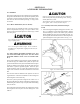
11.3.1 Assembly Instructions (Standard and Super
Track)
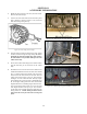
1. Join 2 track segments together, lining up the 1/4" holes. See
Fig. 11-1. Hammer a track pin through the holes, placing
the lock bushing as shown in the centre space provided.
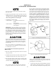
When installing the track pins which hold the track seg-
ments together, alternate the direction in which the pins are
pushed through the track segment holes. See Fig. 11-2.
Figure 11-1. Track Assembly.
Figure 11-2. Track Assembly.