improve your life Improve your life TECHNICAL DATA MINI MULTISET V.R.F.
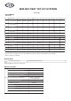
MINI-MULTISET VRF DCI SYSTEMS AS Line-up R410A Models Indoor Units Indoor Unit Indoor UnitType T ype 22 28 36 56 45 64 AS1S** 1-Way Air Discharge Discharge 1-W ay Air Semi-Concealed Semi-Concealed ASBS** 1-Way Discharge 1-W ay Air Discharge S emi-C oncealed Slim S emi-C oncealed S lim AS2S** 2-W 2-W ay ayAir Air Discharge Discharge 2-Way Discharge Semi-Concealed Semi-Concealed Semi-Concealed AS2S22MH ASS 4-W 4-W ay ayAir Air AirDischarge Discharge Discharge 4-Way Semi-Concealed Semi-Conceal
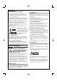
IMPORTANT! Please Read Before Starting When Installing… This air conditioning system meets strict safety and operating standards. As the installer or service person, it is an important part of your job to install or service the system so it operates safely and efficiently. …In a Room Properly insulate any tubing run inside a room to prevent “sweating” that can cause dripping and water damage to walls and floors.
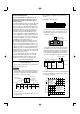
Check of Density Limit 2. The standards for minimum room volume are as follows. The room in which the air conditioner is to be installed requires a design that in the event of refrigerant gas leaking out, its density will not exceed a set limit. The refrigerant (R410A), which is used in the air conditioner, is safe, without the toxicity or combustibility of ammonia, and is not restricted by laws imposed to protect the ozone layer.
Mini Multiset VRF DCI Contents 1. Outiline of Mini Multiset 1. Line-up . . . . . . . . . . . . . . . . . . . . . . . . . . . . . . . . . . . . . . . . . . . . . . . . . . . . . . . . . . . . . . . 1-2 2. Design of Mini Multiset 1. Model Selecting and Capacity Calculator . . . . . . . . . . . . . . . . . . . . . . . . . . . . . . . . . . . 2-2 2. System Design . . . . . . . . . . . . . . . . . . . . . . . . . . . . . . . . . . . . . . . . . . . . . . . . . . . . . . . . 2-13 3. Installation Instructions .
Outline of Mini Multiset Contents 1. Outiline of Mini Multiset 1. Line-up . . . . . . . . . . . . . . . . . . . . . . . . . . . . . . . . . . . . . . . . . . . . . . . . . . . . . . . . . . . . . . .
Outline of Mini Multiset 1. Line-up Outdoor units DC inverter unit Type AES 04 MMIH AES 05 MMIH AES 06 MMIH Capacity: kW (BTU/h) 11.2 (38,200) 14.0 (47,800) 15.5 (52,900) Cooling / Heating / 12.5 (42,700) / 16.0 (54,600) / 17.
Design of Mini Multiset 2. Design of Mini Multiset 1. Model Selecting and Capacity Calculator . . . . . . . . . . . . . . . . . . . . . . . . . . . . . . . . . . . 2-2 2. System Design . . . . . . . . . . . . . . . . . . . . . . . . . . . . . . . . . . . . . . . . . . . . . . . . . . . . . . . . 2-13 3. Installation Instructions . . . . . . . . . . . . . . . . . . . . . . . . . . . . . . . . . . . . . . . . . . . . . . . . . 2-25 4. Electrical Wiring . . . . . . . . . . . . . . . . . . . . . . . . . . . .
Design of Mini Multiset 1. Model Selecting and Capacity Calculator 1-1. Operating Range Heating Cooling 25 45 43 20 35 15 Outdoor air intake temp. °C (WB) 40 2 Outdoor air intake temp. °C (DB) 30 25 Operating range 20 15 10 5 Operating range 0 –5 –10 10 –15 5 –20 0 10 15 20 25 30 35 Indoor air intake temp. °C (DB) –5 –10 –15 14 10 15 20 25 30 Indoor air intake temp.
Design of Mini Multiset 1. Model Selecting and Capacity Calculator 1-2. Procedure for Selecting Models and Calculating Capacity ■ Model Selection Procedure Select the model and calculate the capacity for each refrigerant system according to the procedure shown below. Calculation of the indoor air-conditioning load ● Calculate the maximum air-conditioning load for each room or zone.
Design of Mini Multiset 1. Model Selecting and Capacity Calculator 1-3. Calculation of Actual Capacity of Indoor Unit ■ Calculating the actual capacity of each indoor unit Because the capacity of a multi air-conditioner changes according to the temperature conditions, tubing length, elevation difference and other factors, select the correct model after taking into account the various correction values. When selecting the model, calculate the corrected capacities of the outdoor unit and each indoor unit.
Design of Mini Multiset 1.
Design of Mini Multiset 1. Model Selecting and Capacity Calculator Indoor unit capacity correction coefficient Refer to the graph below for the correction coefficients for Ruc and Ruh. 2 Indoor unit capacity correction coefficient for Ruc (cooling) Indoor unit capacity correction coefficient for Ruh (heating) 1.0 0.9 0.8 0.7 0.6 0.5 0.4 0.5 0.6 0.7 0.8 0.9 1.0 1.1 1.2 1.3 1.4 1.5 1.6 1.7 Corrected indoor/outdoor capacity ratio (Ruc or Ruh) 1.8 1.9 2.
Design of Mini Multiset 1. Model Selecting and Capacity Calculator Outdoor unit heating capacity characteristics AES 05 MMIH 130 ( C DB) 120 15 110 20 100 90 25 80 70 60 50 0 40 –20 –15 –10 –5 0 5 10 15 Outdoor air intake temp. ( C DB) Capacity ratio (%) Capacity ratio (%) AES 04 MMIH 130 120 110 100 90 80 70 60 50 0 40 –20 –15 –10 –5 ( C DB) 15 20 25 0 5 10 2 15 Outdoor air intake temp.
Design of Mini Multiset 1. Model Selecting and Capacity Calculator ■ Graph of indoor unit capacity characteristics (2 – (1)) 2 indicates the rating point. 120 110 100 90 80 14 15 16 17 18 19 20 21 22 23 24 25 Indoor air intake temp. (°C WB) Indoor unit heating capacity characteristics Rate of heating capacity change (%) Rate of cooling capacity change (%) Indoor unit cooling capacity characteristics indicates the rating point.
Design of Mini Multiset 1. Model Selecting and Capacity Calculator 1-4. Capacity Correction Graph According to Temperature Condition ■ Capacity characteristics (The corrected capacity for specific temperature conditions can be found from the graphs below and next page.) Capacity ratio (%) 120 22WB 100 104 (1) 100 (2) 90 (1) 80 (2) 19WB 80 16WB 35 –10 38 (1) AES 04 MMIH AES 05 MMIH (2) AES 06 MMIH 43 Outdoor air intake temp.
Design of Mini Multiset 1. Model Selecting and Capacity Calculator Input ratio (%) 2 130 120 110 100 90 80 70 60 50 40 ( C DB) 15 20 25 130 120 110 15 100 90 20 80 70 25 60 50 –20 –15 –10 –5 0 5 10 15 Outdoor air intake temp. ( C DB) Capacity ratio (%) AES 05 MMIH Input ratio (%) Capacity ratio (%) AES 04 MMIH 130 120 110 100 90 80 70 60 50 40 ( C DB) 15 20 25 130 120 110 100 90 80 70 60 50 –20 –15 –10 –5 15 20 25 0 5 10 15 Outdoor air intake temp.
Design of Mini Multiset 1. Model Selecting and Capacity Calculator ● Inverter model rated performance values Item Cooling Heating Model (SPW-) Cooling capacity (kW) Power consumption (kW) Heating capacity (kW) Power consumption (kW) AES 04 MMIH 11.2 2.76 12.5 2.88 AES 05 MMIH 14.0 3.83 16.0 3.90 AES 06 MMIH 15.5 4.57 17.6 4.58 ■ Outdoor unit heating capacity correction coefficient during frosting/defrosting (1 – (3)) Outdoor intake air temp.
Design of Mini Multiset 1. Model Selecting and Capacity Calculator For CR365, 485GX(H)56 units ■ If the maximum tubing length (L1) exceeds 90 m (equivalent length), increase the tubing size of the main gas tube (LM) by one rank. * The size increase is applied to the gas tube only. In addition, for a 6 HP unit it is not necessary to increase the tubing size. ■ Increasing the tubing size of the gas tubes can reduce the loss of capacity caused by longer tubing lengths.
Design of Mini Multiset 2. System Design 2-1. 1. 2. 3. 4. 5. 6. 7. 8. 9. 10. 11. 12. 13. 14. 15. 2-3.
Design of Mini Multiset 2. System Design 2-5. Tubing Size Table 2-2 Main Tubing Size (LA) kW System horsepower 11.2 14.0 15.5 4 5 6 Gas tubing (mm) ø15.88 Liquid tubing (mm) 2 ø19.05 ø9.52 Unit: mm Table 2-3 Main Tubing Size After Distribution (LB, LC...) Below kW Total capacity after distribution Tubing size 7.1 11.2 14.0 15.5 (2.5 hp) (4 hp) (5 hp) (6 hp) 7.1 – Over kW (2.5 hp) Gas tubing (mm) ø12.7 Liquid tubing (mm) ø9.52 ø15.88 ø19.05 ø9.
Design of Mini Multiset 2. System Design 2-7. Additional Refrigerant Charge Additional refrigerant charge amount is calculated from the liquid tubing total length as follows. Table 2-7 Amount of Refrigerant Charge Per Meter, According to Liquid Tubing Size Liquid tubing size Amount of refrigerant charge/m (g/m) ø6.35 26 Required amount of charge = (Amount of refrigerant charge per meter of each size of liquid tube × its tube length) + (...) + (...) ø9.
Design of Mini Multiset 2. System Design Table 2-10 Ranges that Apply to Refrigerant Tubing Lengths and to Differences in Installation Heights Items Marks Contents L1 L (L2 – L3) Allowable tubing length 1 1 + 2 +~ H1 Allowable elevation difference H2 n n–1 +L1 Equivalent length > 175 Difference between max. length and min . length from the No.1 distribution joint > 40 Max. length of each distribution tube > 30 Total max.
Design of Mini Multiset 2. System Design 2-11. System Example (1) Below are the tables created using the “Sanyo PAC/GHP System Diagram Software.” Details of the calculations are shown in (2). Outdoor unit 50 m Elevation difference: 10 m Indoor unit 1 10 m 20 m 20 m 10 m 10 m 10 m Indoor unit 2 Indoor unit 3 Indoor unit 4 2 Selection conditions Assumes that installation is in a 50 Hz region. Outdoor unit Selected model AES 04 MMIH Air condition Cooling (DB/WB) Max. load (kW) 33.0 / 22.
Design of Mini Multiset 2. System Design Indoor unit changes The indoor unit in room 4, where the corrected indoor unit capacity is less than the maximum load, is increased by one rank. Outdoor unit Selected model AES 06 MMIH Room 1 Room 2 (indoor unit 1) (indoor unit 2) Type 56 Type 22 Maximum load (cooling/heating) (kW) Rated capacity (cooling/heating) (kW) 5.4 / 5.6 1.8 / 2.3 2.1 / 2.3 2.1 / 2.3 16.0 / 18.0 5.6 / 6.3 2.2 / 2.5 2.2 / 2.5 2.8 / 3.2 12.77 / 14.85 5.60 / 5.96 2.20 / 2.35 2.
Design of Mini Multiset 2. System Design 2-12. Example of Tubing Size Selection and Refrigerant Charge Amount Additional refrigerant charging Based on the values in Tables 2-2, 2-3, 2-4 and 2-7, use the liquid tubing size and length, and calculate the amount of additional refrigerant charge using the formula below. Required additional –3 refrigerant charge (kg) = [56 × (a) + 26 × (b)] × 10 (a): Liquid tubing ● Total length of ø9.52 (m) (b): Liquid tubing Total length of ø6.
Design of Mini Multiset 2. System Design Example: L1 L2 LA LB Main tube of unit LC LN n 1st branch Unit distribution tube 2 1 model 22 2 3 model 28 model 56 n–1 model 36 model 45 ● Example of each tubing length Main tubing Distribution joint tubing LA = 40 m Indoor side LB = 5 m 1=5m 4=6m LC = 5 m 2=5m 5=5m LD = 15 m = 2 m 3 ● Obtain charge amount for each tubing size Note that the charge amounts per 1 meter are different for each liquid tubing size. ø9.
Design of Mini Multiset 2. System Design 2-13. Installing Distribution Joint Tube branching methods (horizontal use) 15 to 30 ° (1) Refer to “HOW TO ATTACH DISTRIBUTION JOINT” enclosed with the optional distribution joint kit (DDVI 16). (2) In order to prevent accumulation of refrigerant oil in stopped units, if the main tubing is horizontal then each branch tubing length should be at an angle that is greater than horizontal.
Design of Mini Multiset 2. System Design 2-14. Optional Distribution Joint Kit See the installation instructions packaged with the distribution joint kit for the installation procedure. Table 2-11 Model name Cooling capacity after distribution DDVI 16 Remarks 22.4 kW or less For indoor unit DDVI 16 Use: For indoor unit (Capacity after distribution joint is 22.4 kW or less.) Example: (F below indicates inner diameter. F below indicates outer diameter.
Design of Mini Multiset 2. System Design Dimensions Unit: mm Figure Type with flare nut at each end Size ø6.35 (1/4") ø9.52 (3/8") ø12.7 (1/2") ø15.88 (5/8") E A Dimensions B 42 42 42 51 C 54 54 58 68 D 16 16 20 22 E 44 44 51 56 C D A 72 76 89 108 Insulator (divided in 2) Service port 30˚ Note: Install the service port so that it faces the extension side. 2 Ball Valve Installation (for refrigerant R410A only) Check the size of the ball valve set you separately purchased.
Design of Mini Multiset 2. System Design 3. Opening and closing the valve This valve is open at the time of shipment from the factory. If the valve is used for extension, be sure to close it. Valve opened Valve closed Spindle 2 Spindle 4. Installing thermal insulation The thermal insulation used for a flare-nut type valve is in the form of a bag. When the valve is used for extension, it can be used as-is.
Design of Mini Multiset 3. Installation Instructions 3-2. Outdoor Unit Exhaust fan AVOID: ● heat sources, exhaust fans, etc. (Fig. 2-6) ● damp, humid or uneven locations Hot air Heat source Outdoor unit DO: 2 ● choose a place as cool as possible. ● choose a place that is well ventilated and outside air temperature does not exceed maximum 45°C constantly. ● allow enough room around the unit for air intake/ exhaust and possible maintenance. (Fig.
Design of Mini Multiset 3. Installation Instructions 3-3. Air Discharge Chamber for Top Discharge Be sure to install an air discharge chamber in the field when: ● it is difficult to keep a space of min. 50 cm between the air discharge outlet and an obstacle. ● the air discharge outlet is facing a sidewalk and discharged hot air may annoy passers-by. Refer to Fig. 2-10. Air discharge 3-4.
Design of Mini Multiset 3. Installation Instructions 1 Unit front, air discharge chamber 2 Unit left side, air discharge chamber 3 Unit light side, air discharge chamber 4 Reinforcement brackets, 4 locations 29.5 300 3-6. Dimensions of Air-Discharge Chamber Reference diagram for air-discharge chamber (field supply) ***A for AES 04-05-06 MMIH 2 240 3 4 240 29.
Design of Mini Multiset 3. Installation Instructions Reference for air-discharge chamber (field supply) Required space around outdoor unit AES 04-05-06 MMIH) with *** If an air discharge chamber is used, the space shown below must be secured around the outdoor unit. If the unit is used without the required space, a protective device may activate, preventing the unit from operating. Min. 200 Min. 1000 (1) Single-unit installation 2 Unit: mm CAUTION The top and both sides must remain open.
Design of Mini Multiset 3. Installation Instructions 3-8.
Design of Mini Multiset 3. Installation Instructions Reference diagram for snow-proof vents – 1 Space requirements for setting – (1) AES 04-05-06 MMIH with *** [Obstacle to the front of unit] [Obstacle to the rear of unit] ● Top is open: (1) Single-unit installation 2 Min. D Min. A Min. H ● Top is open: (1) Single-unit installation (2) Obstacles on both sides Min. B (2) Multiple-unit installation (2 or more units) Min. C Min. I Min. G Min. I Min.
Design of Mini Multiset 3. Installation Instructions Reference diagram for snow-proof vents – 2 Space requirements for setting – (2) AES 04-05-06 MMIH with *** [Obstacles to the front and rear of unit] • The top and both sides must remain open. Either the obstacle to the front or the obstacle to the rear must be no taller than the height of the outdoor unit. Min. O 2 Q Min.
Design of Mini Multiset 3. Installation Instructions 3-10. Installing the Outdoor Unit ● Ordinarily, ensure a base height of 5 cm or more. If a drain pipe is used, or for use in cold-weather regions, ensure a height of 15 cm or more at the feet on both sides of the unit. (In this case, leave clearance below the unit for the drain pipe, and to prevent freezing of drainage water in cold-weather regions.) ● Refer to the Fig. 3-1 for the anchor bolt dimensions.
Design of Mini Multiset 4. Electrical Wiring 4-1. General Precautions on Wiring (1) Before wiring, confirm the rated voltage of the unit as shown on its nameplate, then carry out the wiring closely following the wiring diagram. (7) Regulations on wire diameters differ from locality to locality. For field wiring rules, please refer to your LOCAL ELECTRICAL CODES before beginning.
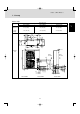
Design of Mini Multiset 4. Electrical Wiring 4-3. Wiring System Diagram Indoor unit (No. 1) L Power supply 220-240V 50Hz N Outdoor unit INV unit 1 3 Ground Remote controller WHT 1 BLK 2 B Power supply 220–240V-1N 50Hz Ground 1 2 U2 D L N C U1 Ground 1 1 2 A L N 2 2 Ground C Indoor unit (No. 2) L Power supply 220-240V 50Hz N 1 2 2 3 Ground Remote controller WHT 1 BLK 2 B U1 U2 D 1 1 2 2 Ground C Indoor unit (No.
Design of Mini Multiset CAUTION (1) When linking outdoor units in a network (S-net link system), disconnect the terminal extended from the short plug (CN003, 2P Black, location: right bottom on the outdoor main control PCB) from all outdoor units except any one of the outdoor units. (When shipping: In shorted condition.) Otherwise the communication of S-net link system is not performed. For a system without link (no connection wiring between outdoor units), do not remove the short plug.
Design of Mini Multiset (5) Use shielded wires for inter-unit control wiring (c) and ground the shield on both sides, otherwise misoperation from noise may occur. (Fig. 4-4) Connect wiring as shown in Section “4-3. Wiring System Diagram.” WARNING Shielded wire Ground Loose wiring may cause the terminal to overheat or result in unit malfunction. A fire hazard may also exist. Therefore, ensure that all wiring is tightly connected. Ground Fig.
Mini Multiset Unit Specifications Contents 3. Mini Multiset unit specifications 1. Outdoor Unit 1-1. 1-2. 1-3. 1-4. 1-5. Specifications . . . . . . . . . . . . . . . . . . . . . . . . . . . . . . . . . . . . . . . . . . . . . . . . . . . . . . . . . . . . . . . . . . . . . 3-3 Major Component Specifications . . . . . . . . . . . . . . . . . . . . . . . . . . . . . . . . . . . . . . . . . . . . . . . . . . . . . . 3-9 Dimensional Data . . . . . . . . . . . . . . . . . . . . . . . . . . . . . . . . . . . .
Mini Multiset Unit Specifications 1. Outdoor Unit 1-1. Specifications Unit specifications (A) MODEL No. Outdoor Unit AES 04 MMIH POWER SOURCE 220 - 230 - 240 V / Single-phase / 50 / 60 Hz PERFORMANCE Capacity kW BTU / h Cooling Heating 11.2 12.5 38,200 42,700 3 Air circulation (Hi) m /min (cu.ft/min) 100 (3,530) ELECTRICAL RATINGS Voltage rating V Available voltage range V Running amperes A 14.8 14.1 13.5 Max. running amperes* A 24.0 24.0 Power input kW 2.76 Max.
Mini Multiset Unit Specifications 1. Outdoor Unit Unit specifications (B) MODEL No. Outdoor Unit AES 05 MMIH POWER SOURCE 220 - 230 - 240 V / Single-phase / 50 / 60 Hz PERFORMANCE Capacity kW BTU / h Cooling Heating 14.0 16.0 47,800 54,600 3 Air circulation (Hi) m /min (cu.ft/min) 100 (3,530) ELECTRICAL RATINGS Voltage rating V Available voltage range V Running amperes A 20.5 19.6 18.8 Max. running amperes* A 24.0 24.0 24.0 Power input kW 3.83 3.83 Max.
Mini Multiset Unit Specifications 1. Outdoor Unit Unit specifications (C) MODEL No. Outdoor Unit AES 06 MMIH POWER SOURCE 220 - 230 - 240 V / Single-phase / 50 / 60 Hz PERFORMANCE Cooling Capacity kW BTU / h Heating 15.5 17.6 52,900 60,000 m3/min (cu.ft/min) Air circulation (Hi) 100 (3,530) ELECTRICAL RATINGS Voltage rating V Available voltage range V Running amperes A 24.4 23.4 22.4 Max. running amperes* A 28.0 28.0 Power input kW 4.57 Max.
Mini Multiset Unit Specifications 1. Outdoor Unit Unit specifications (D) MODEL No. Outdoor Unit AES 04 MMIH POWER SOURCE 220 - 230 - 240 V / Single-phase / 50 / 60 Hz PERFORMANCE Cooling Capacity 11.2 kW BTU / h 38,200 3 Air circulation (Hi) m /min (cu.ft/min) 100 (3,530) ELECTRICAL RATINGS Voltage rating V Available voltage range V Running amperes A 14.8 14.1 13.5 Max. running amperes* A 24.0 24.0 24.0 Power input kW 2.76 2.76 2.76 Max. power input* kW 4.90 4.90 4.
Mini Multiset Unit Specifications 1. Outdoor Unit Unit specifications (E) MODEL No. Outdoor Unit AES 05 MMIH POWER SOURCE 220 - 230 - 240 V / Single-phase / 50 / 60 Hz PERFORMANCE Cooling Capacity 14.0 kW BTU / h 47,800 m3/min (cu.ft/min) Air circulation (Hi) 100 (3,530) ELECTRICAL RATINGS Voltage rating V Available voltage range V Running amperes Max. running amperes* 220 230 240 A 20.5 19.6 18.8 A 24.0 24.0 24.0 Power input kW 3.83 3.83 3.83 Max. power input* kW 4.
Mini Multiset Unit Specifications 1. Outdoor Unit Unit specifications (F) MODEL No. Outdoor Unit AES 06 MMIH POWER SOURCE 220 - 230 - 240 V / Single-phase / 50 / 60 Hz PERFORMANCE Cooling Capacity 15.5 kW BTU / h 52,900 m3/min (cu.ft/min) Air circulation (Hi) 100 (3,530) ELECTRICAL RATINGS Voltage rating V Available voltage range V Running amperes A 24.4 23.4 22.4 Max. running amperes* A 28.0 28.0 28.0 Power input kW 4.57 4.57 4.57 Max. power input* kW 5.72 5.72 5.
Mini Multiset Unit Specifications 1. Outdoor Unit 1-2. Major Component Specifications Outdoor unit (A) MODEL No. AES 04 MMIH Power source 220 - 230 - 240 V / 1N / 50 Hz Controller P.C.B. Ass’y CR-CR365GXH56 Control circuit fuse 250V, 6.3A Compressor INV (Inverter) Type Rotary (Hermetic) Model ... Code No. Motor rated output Compressor oil (ETHER FV68S) C-9RVN273H0T ... 808673805 kW 2.1 cc 1,900 Coil resistance (Ambient temperature 25°C) V - U: 0.138, U - W: 0.138 W - V: 0.
Mini Multiset Unit Specifications 1. Outdoor Unit Outdoor unit (B) MODEL No. AES 05 MMIH Power source 220 - 230 - 240 V / 1N / 50 Hz Controller P.C.B. Ass’y CR-CR365GXH56 Control circuit fuse 250V, 6.3A Compressor INV (Inverter) Type Rotary (Hermetic) Model ... Code No. Motor rated output Compressor oil (ETHER FV68S) C-9RVN273H0T ... 808673805 kW 3.3 cc 1,900 Coil resistance (Ambient temperature 25°C) V - U: 0.138, U - W: 0.138 W - V: 0.
Mini Multiset Unit Specifications 1. Outdoor Unit Outdoor unit (C) MODEL No. AES 06 MMIH Power source 220 - 230 - 240 V / 1N / 50 Hz Controller P.C.B. Ass’y CR-CR605GXH56 Control circuit fuse 250V, 6.3A Compressor INV (Inverter) Type Rotary (Hermetic) Model ... Code No. Motor rated output Compressor oil (ETHER FV68S) C-9RVN273H0T ... 808673805 kW 4.0 cc 1,900 Coil resistance (Ambient temperature 25°C) V - U: 0.138, U - W: 0.138 W - V: 0.
Mini Multiset Unit Specifications 1. Outdoor Unit Outdoor unit (D) MODEL No. AES 04 MMIH Power source 220 - 230 - 240 V / 1N / 50 Hz Controller P.C.B. Ass’y Compressor CR-CR365GXH56 INV (Inverter) Type Rotary (Hermetic) Model ... Code No. Motor rated output Compressor oil (ETHER FV68S) C-9RVN273H0T ... 808673805 kW 2.1 cc 1,900 Coil resistance (Ambient temperature 25°C) V - U: 0.138, U - W: 0.138 W - V: 0.
Mini Multiset Unit Specifications 1. Outdoor Unit Outdoor unit (E) MODEL No. AES 05 MMIH Power source 220 - 230 - 240 V / 1N / 50 Hz Controller P.C.B. Ass’y CR-CR365GXH56 Control circuit fuse 250V, 6.3A Compressor INV (Inverter) Type Rotary (Hermetic) Model ... Code No. Motor rated output Compressor oil (ETHER FV68S) C-9RVN273H0T ... 808673805 kW 3.3 cc 1,900 Coil resistance (Ambient temperature 25°C) V - U: 0.138, U - W: 0.138 W - V: 0.
Mini Multiset Unit Specifications 1. Outdoor Unit Outdoor unit (F) MODEL No. AES 06 MMIH Power source 220 - 230 - 240 V / 1N / 50 Hz Controller P.C.B. Ass’y CR-CR605GXH56 Control circuit fuse 250V, 6.3A Compressor INV (Inverter) Rotary (Hermetic) Type Model ... Code No. Motor rated output Compressor oil (ETHER FV68S) C-9RVN273H0T ... 808673805 kW 4 cc 1,900 Coil resistance (Ambient temperature 25°C) V - U: 0.138, U - W: 0.138 W - V: 0.
Electrical wiring port (ø1.9) Electrical wiring port (ø1.6) Auxiliary connection tube (ø15.88 to ø19.05), 6 hp only 7 8 9 13 70 66 6 60 5 Wind direction 13 940 219 150 Wind direction 13 13 Electrical wiring port (ø2.9) 6 170 Electrical wiring port (ø3.8) 340 5 296 Refrigerant tubing port 1230 4 18 110 99 20 9 3 2 8 7 4 Wind direction 2 x ø32 holes (holes for drain) Of the 4 ø32 holes, use 1 of the 2 holes specified for drain use to install the drain port.
Mini Multiset Unit Specifications 1. Outdoor Unit 1-4. Refrigerant Flow Diagram AES 04 MMIH AES 05 MMIH AES 06 MMIH 6 Discharge HPS Suction Connection diameter ø15.88 mm LP removal HP removal STF – 0401G Cooling cycle Heating cycle Brazing BCuP – 3 Outside air C1 UKV – 30D40 3 AES 04 MMIH AES 05 MMIH AES 06 MMIH Discharge HPS Suction Connection diameter ø15.
Mini Multiset Unit Specifications 1. Outdoor Unit 1-5. Sound Data (1) Sound Power Level AES 04 MMIH AES 05 MMIH 6 Model Sound Power Level AES 04 MMIH AES 05 MMIH 67 dB (A) Cooling Condition 90 80 NC – 70 Sound Power Level (dB) 70 60 NC – 60 50 NC – 50 40 NC – 40 30 NC – 30 20 10 NC – 20 63 125 250 500 1000 2000 4000 Frequency at center of sound pressure band (Hz) NOTE 1. dBA = A – weighted sound power level (A – scale according to IEC) 2.
Mini Multiset Unit Specifications 1. Outdoor Unit AES 06 MMIH Model AES 06 MMIH Sound Power Level 68 dB (A) Cooling Condition 90 80 NC – 70 3 Sound Power Level (dB) 70 60 NC – 60 50 NC – 50 40 NC – 40 30 NC – 30 20 10 NC – 20 63 125 250 500 1000 2000 4000 Frequency at center of sound pressure band (Hz) NOTE 1. dBA = A – weighted sound power level (A – scale according to IEC) 2.
Mini Multiset Unit Specifications 1. Outdoor Unit (2) Sound Pressure Level AES 04 MMIH AES 05 MMIH 6 AES 04 MMIH AES 05 MMIH Sound Pressure Level Front 51 dB (A) Cooling Quiet Mode 48 dB (A) Model 1 m in front at height of 1.
Mini Multiset Unit Specifications 1. Outdoor Unit AES 06 MMIH Model AES 06 MMIH Sound Pressure Level Cooling Front 52 dB (A) Quiet Mode 49 dB (A) Condition 1 m in front at height of 1.5 m Front Quiet Mode 90 80 NC – 70 3 Octave Band Level (dB)* 70 60 NC – 60 50 NC – 50 40 NC – 40 30 20 NC – 30 Approximate minimum audible limit for continuous noise 10 Overall 63 125 NC – 20 250 500 1000 2000 4000 Frequency at center of sound pressure band (Hz) * 0 dB = 0.
Test Run and Others Contents 4. Test Run and Others 1. Air Purging . . . . . . . . . . . . . . . . . . . . . . . . . . . . . . . . . . . . . . . . . . . . . . . . . . . . . . . . . . . .4-2 2. Test Run . . . . . . . . . . . . . . . . . . . . . . . . . . . . . . . . . . . . . . . . . . . . . . . . . . . . . . . . . . . . . .-45 2-1. 2-2. 2-3. 2-4 2-5. 2-6. Preparing for Test Run . . . . . . . . . . . . . . . . . . . . . . . . . . . . . . . . . . . . . . . . . . . . . . . . . . . . . . . . . . . . . .
Test Run and Others 1. Air Purging Air and moisture in the refrigerant system may have undesirable effects as indicated below. Manifold gauge pressure in the system rises operating current rises cooling (or heating) efficiency drops moisture in the refrigerant circuit may freeze and block capillary tubing water may lead to corrosion of parts in the refrigerant system Fig.
Test Run and Others 1. Air Purging (3) Do a leak test of all joints of the tubing (both indoor and outdoor) and both gas tube and liquid tube service valves. Bubbles indicate a leak. Wipe off the soap with a clean cloth after the leak test. Manifold valve (4) After the system is found to be free of leaks, relieve the nitrogen pressure by loosening the charge hose connector at the nitrogen cylinder. When the system pressure is reduced to normal, disconnect the hose from the cylinder.
Test Run and Others 1. Air Purging CAUTION Use a cylinder designed for use with R410A respectively. Manifold valve Pressure gauge Charging additional refrigerant Lo Hi Charging additional refrigerant (calculated from the liquid tube length as shown in Section 2. 2-7 “Additional Refrigerant Charge”) using the liquid tube service valve. (Fig. 5-5) Use a balance to measure the refrigerant accurately.
Test Run and Others 2. Test Run 2-1. Preparing for Test Run Before attempting to start the air conditioner, check the following. ON (1) All loose matter is removed from the cabinet, especially steel filings, bits of wire, and clips. (Power must be turned ON at least 5 hours before attempting test run) (2) The control wiring is correctly connected and all electrical connections are tight. (3) The transportation pads for the indoor fan have been removed. If not, remove them now.
Test Run and Others 2. Test Run Items to Check Before the Test Run 2-2. Test Run Procedure 1. Turn the remote power switch on at least 5 hours before the test, in order to energize the crank case heater. Recheck the items to check before the test run. 2. Turn the outdoor service valves (2 locations) to the full-open positions. Set the unit address. Set the No. of outdoor units. Unit No. setting switch (S004) Set the No. of indoor units.
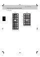
Test Run and Others 2. Test Run 2-3. Outdoor Unit PCB Setting CN33 4 S003 CN51 CN50 S002 D043 (LED2) S004 D042 (LED1) Fig.
Test Run and Others 2. Test Run Examples of the No. of indoor units settings No. of indoor units Indoor unit setting (S004) (Rotary switch, red) 1 1 unit (factory setting) Set to 2 9 9 units 2 2 units Set to 1 Set to 9 Examples of refrigerant circuit (R.C.) address settings (required when link wiring is used) System address No.
Test Run and Others 2. Test Run 2-4. Auto Address Setting Basic wiring diagram: Example (1) • If link wiring is not used (The inter-unit control wires are not connected to multiple refrigerant systems.) Indoor unit addresses can be set without operating the compressors. No. 1 unit settings (S004) System address (system 1 setting) (S003) ON 1 2 No. of indoor units (8 units setting) (S004) (S002) ON 1 8 OFF Unit No.
Test Run and Others 2. Test Run Basic wiring diagram: Example (2) If link wiring is used No. 1 unit settings No. of indoor units (6 units setting) System address (system 1 setting) (S003) (S004) (S002) ON ON * When multiple outdoor units exist, remove the socket that is used to short-circuit the terminal plug (CN33) from all outdoor unit PCBs except for 1. Alternatively, move the sockets to the “OPEN” side.
Test Run and Others 2. Test Run Case 1 Automatic Address Setting (no compressor operation) Indoor and outdoor unit power can be turned ON for each system separately. Indoor unit addresses can be set without operating the compressors. Automatic Address Setting from Outdoor Unit 1. On the outdoor unit control PCB, check that the system address rotary switch (S002) is set to “1” and that the ON (These are the settings at the time of factory shipment.) DIP switch (S003) is set to “0.” ON 1 2 OFF 2.
Test Run and Others 2. Test Run Case 2 Automatic Address Setting in Heating Mode Indoor and outdoor unit power cannot be turned ON for each system separately. In the following, automatic setting of indoor unit addresses is not possible if the compressors are not operating. Therefore perform this process only after completing all refrigerant tubing work. Automatic Address Setting from Outdoor Unit 1. Perform steps 1 and 2 in the same way as for Case 1 . 2.
Test Run and Others 2. Test Run Case 3 Automatic Address Setting in Cooling Mode Indoor and outdoor unit power cannot be turned ON for each system separately. In the following, automatic setting of indoor unit addresses is not possible if the compressors are not operating. Therefore perform this process only after completing all refrigerant tubing work. Automatic address setting can be performed during Cooling operation. Automatic Address Setting from Outdoor Unit 1.
Test Run and Others 2. Test Run Display during automatic address setting On outdoor unit PCB LED 2 1 Blink alternately * Do not short-circuit the automatic address setting pin (CN51) again while automatic address setting is in progress. Doing so will cancel the setting operation and will cause LEDs 1 and 2 to turn OFF. * When automatic address setting has been successfully completed, both LEDs 1 and 2 turn OFF. * LED 1 is D042. LED 2 is D043.
Test Run and Others 2. Test Run Request concerning recording the indoor/outdoor unit combination Nos. After automatic address setting has been completed, be sure to record them for future reference. List the outdoor unit system address and the addresses of the indoor units in that system in an easily visible location (next to the nameplate), using a permanent marking pen or similar means that cannot be erased easily.
Test Run and Others 2. Test Run 2-5. Caution for Pump Down Pump down means refrigerant gas in the system is returned to the outdoor unit. Pump down is used when the unit is to be moved, or before servicing the refrigerant circuit. This outdoor unit cannot collect more than the rated refrigerant amount as shown by the nameplate on the back. If the amount of refrigerant is more than that recommended, do not conduct pump down. In this case use another refrigerant collecting system. CAUTION 2-6.
Test Run and Others 2. Test Run Alarm message Possible cause of malfunction Serial communication errors Mis-setting Improper setting. This alarm message shows when the indoor unit for multiple-use is not connected to the outdoor unit. Duplication of main indoor unit address setting in group control. Duplication of outdoor R.C. address setting. Thermistor fault Indoor thermistor is either open or damaged. Outdoor thermistor is either open or damaged.
Test Run and Others 3. Electrical Wiring 3-1. General Precautions on Wiring (1) Before wiring, confirm the rated voltage of the unit as shown on its nameplate, then carry out the wiring closely following the wiring diagram. (7) Regulations on wire diameters differ from locality to locality. For field wiring rules, please refer to your LOCAL ELECTRICAL CODES before beginning.
Test Run and Others 3. Electrical Wiring 3-3. Wiring System Diagram Indoor unit (No. 1) L Power supply 220-240V 50Hz N Outdoor unit INV unit 1 3 Ground Remote controller WHT 1 BLK 2 B Power supply 220–240V-1N 50Hz Ground 1 2 U2 Ground 1 1 2 L N C U1 D A L N 2 2 Ground C Indoor unit (No. 2) L Power supply 220-240V 50Hz N 1 2 3 Ground Remote controller WHT 1 BLK 2 B U1 U2 D 1 1 2 2 Ground C Indoor unit (No.
Test Run and Others 3. Electrical Wiring CAUTION (1) When linking outdoor units in a network (S-net link system), disconnect the terminal extended from the short plug (CN003, 2P Black, location: right bottom on the outdoor main control PCB) from all outdoor units except any one of the outdoor units. (When shipping: In shorted condition.) Otherwise the communication of S-net link system is not performed. For a system without link (no connection wiring between outdoor units), do not remove the short plug.
Test Run and Others 3. Electrical Wiring (5) Use shielded wires for inter-unit control wiring (c) and ground the shield on both sides, otherwise misoperation from noise may occur. (Fig. 5-16) Connect wiring as shown in Section “3-3. Wiring System Diagram.” WARNING Shielded wire Ground Loose wiring may cause the terminal to overheat or result in unit malfunction. A fire hazard may also exist. Therefore, ensure that all wiring is tightly connected. Ground Fig.
Test Run and Others 4. Installation Standards 2. The standards for minimum room volume are as follows. 4-1. Check of Density Limit The room in which the air conditioner is to be installed requires a design that in the event of refrigerant gas leaking out, its density will not exceed a set limit. The refrigerant (R410A), which is used in the air conditioner, is safe, without the toxicity or combustibility of ammonia, and is not restricted by laws imposed to protect the ozone layer.
Test Run and Others 4. Installation Standards 4-2. Precautions for Installation Using New Refrigerant 4-2-1. Care regarding tubing (1) Process tubing Material: Use C1220 phosphorous deoxidized copper specified in JIS H3300 “Copper and Copper Alloy Seamless Pipes and Tubes.” Tubing size: Be sure to use the sizes indicated in the table below. Use a tube cutter when cutting the tubing, and be sure to remove any flash. This also applies to distribution joints (optional).
Test Run and Others 4. Installation Standards (2) Use R410A exclusive cylinder only. Valve Single-outlet valve (with siphon tube) Liquid refrigerant should be recharged with the cylinder standing on end as shown.
Via Varese, 90 - 21013 Gallarate - Va - Italy Tel. +39 0331 755111 - Fax +39 0331 776240 www.argoclima.