
Technical data


2
2 - 24
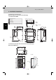
Design of Mini Multiset
2. System Design
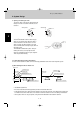
2-14. Recommended Location of Ball Valves
● Select a valve location that allows service to be easily provided for each unit or each refrigerant system.
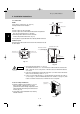
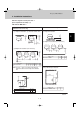
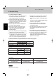
(1) When adding ball valve for indoor unit
1. Location: Install the ball valve at the distribution tube (not main tube).
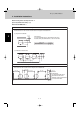
2. Installation requirements
• Be sure to install the ball valve up-grade to prevent the inadvertent flow of oil.
• Install the ball valve at the shortest distance (within 40 cm) from the main tube. If the diameter of the ball valve
is smaller than that of the main tube, use a reducer or the like to reduce the size of the tubing at that location.
• Select a place where it is easy to operate, using careful consideration of the location in advance.
Outdoor unit
Distribution tube
Distribution joint
Main tube
Ball valve (for extension)
Less than 40 cm
Indoor unit for extension
Distribution tube
Main tube
Ball valve (for extension)
Indoor unit for extension
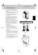
3. Opening and closing the valve
This valve is open at the time of shipment from the
factory. If the valve is used for extension, be sure
to close it.
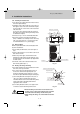
4. Installing thermal insulation
The thermal insulation used for a flare-nut type
valve is in the form of a bag. When the valve is
used for extension, it can be used as-is. If the
valve is used for any other purpose, use a box
cutter or similar tool to cut away the part shown in
the figure at right.
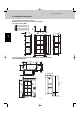
The insulation is divided into 2 parts. After per-
forming the leak test, use vinyl tape or other
means to temporarily fasten the 2 parts together.
Then carry out final finishing.
Valve opened
Spindle
Valve closed
Spindle
Notch
Insulator