"AT" SERIES ELECTRIC HOT WATER BOILERS installation MANUAL AND OPERATING INSTRUCTIONS FOR FORCED HOT WATER ARGO (Technical Support) 2201 Dwyer Avenue Utica, NY 13501 (Corporate Sales) 85 Middle Road Dunkirk, NY 14048 www.argocontrols.com R An ISO 9001-2000 Certified Company P/N I80, Rev.
INSTALLATION MANUAL AND OPERATING INSTRUCTIONS TABLE OF CONTENTS SAFETY SYMBOLS Safety Symbols .................................................... 2 Warnings............................................................... 3 Introduction............................................................ 3 Product Description............................................... 3 Voltage Rating Tables............................................ 4 Installation Procedure............................................
WARNINGS ! WARNING INTRODUCTION ! This manual is intended to familiarize the installer and user of the Electric Hydronic Block with its installation, operation and maintenance so as to assure its normal trouble free operation. 1. Boiler sizing is crucial.
PRODUCT DESCRIPTION continued The following important product information is located on the cabinet cover: ARGO Electric Boilers are controlled by a electronic temperature controller. The controller controls the boiler water temperature with multiple stages and turns stages on based on the heating demand, and the preset boiler outlet water temperature. The controller also can control 120Vac circulating pumps rated up to 5A.
installation procedure Improper installation, adjustment, alteration, service or maintenance can cause injury or property damage. Install unit with a minimum clearance from top of unit to ceiling of 16 inches. If minimum requirements of space are used, it is suggested that the enclosure be exposed to some means of ventilation. The electric Hydronic Block unit must be mounted level, using the top of the back plate as a leveling point. 1.
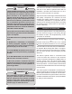
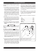
at the bottom of the unit. Reverse flow will result in a noisy operation and cause very early element failure. The drain cock is to be located at the lowest point of piping. DESIGN OF WATER CIRCULATING SYSTEM System should be designed as primary/secondary piping and to operate with a maximum output temperature of 180º F or lower and a temperature rise across the unit of 20º F or lower. Refer to tables below and Figures 2 & 3. 5.
primary/secondary piping FIGURE 2 primary/secondary piping for Multiple zoning with circulators FIGURE 3 primary/secondary piping for Multiple zoning with ZONE VALVES 7
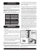
connecting electrical power supply Thermostat: Connect thermostat or zone valve end switch to terminals TT and TT (Figure 4). Do not apply an external power source to these terminals!! Strip wire ends before inserting into terminal block. Tighten terminal screw clamps. WIRING THE BOILER ! WARNING ! Do not use aluminum wire!! FIGURE 4 Argo Electric Hydronic Boilers are pre-wired for use with 240-volt, 3 wire, single-phase, 50/60-hertz power.
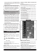
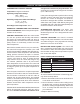
ampacity and temperature. Use copper wire only with insulation rated for 75 °C. Check state and local requirements. Control Board Power Consumption: 0.8A max. LED Display Lights (Figure 6): A total of 8 LED indicator lights display the following information: NOTE: Read the data name plate before connecting unit so that you will become familiar with the specifications. All electrical connections to the unit are provided and located for ease of proper installation.
Control Information continued energized for 3 minutes to purge the boiler. After 3 minutes the control will de-energize the circulator ("Circ" LED turns off).
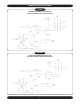
WHT (BLANC) L1 H2 H1 L1 L2 WHT (BLANC) L2 11 NOT USED (NON UTILISÉ) NOT USED (NON UTILISÉ) NOT USED (NON UTILISÉ) NOT USED (NON UTILISÉ) H2 ELEMENT #2 RELAYS (RELAIS DE ĽÉLÉMENT No2) WHT/BLK (BLANC/NOIR) ELEMENT #2 (ÉLÉMENT No2) H1 ELEMENT #1 RELAYS (RELAIS DE ĽÉLÉMENT No1) WHT/BLK (BLANC/NOIR) ELEMENT #1 (ÉLÉMENT No1) 2 3 4 160 170 180 4 20 FAULT (DÉFAILLANCE) 16 C2 N CIRCULATOR PUMP, BY OTHERS (POMPE DE ĽACCELERTEUR, OU AUTRES) 120VAC CIRC C1 L TRANSFORMER (TRANSFORMATEUR)
ELEMENT #2 (ÉLÉMENT No2) H1 L1 WHT (BLANC) L1 L2 WHT (BLANC) L2 12 NOT USED (NON UTILISÉ) NOT USED (NON UTILISÉ) NOT USED (NON UTILISÉ) NOT USED (NON UTILISÉ) H2 ELEMENT #2 RELAYS (RELAIS DE ĽÉLÉMENT No2) H2 H1 ELEMENT #1 RELAYS (RELAIS DE ĽÉLÉMENT No1) WHT/BLK (BLANC/NOIR) ELEMENT #1 (ÉLÉMENT No1) WHT/BLK (BLANC/NOIR) 120 2 3 160 170 180 4 130 140 150 4 16 20 FAULT (DÉFAILLANCE) 12 C2 C1 CIRCULATOR PUMP, BY OTHERS (POMPE DE ĽACCELERTEUR, OU AUTRES) 120VAC CIRC N L TRANSF
WHT (BLANC) 13 WHT (BLANC) ELEMENT #4 (ÉLÉMENT No4) H2 H1 L1 L2 H3 H2 L1 L2 WHT (BLANC) L1 L2 WHT (BLANC) H4 L2 WHT/BLK (BLANC/NOIR) WHT (BLANC) ELEMENT #4 RELAYS (RELAIS DE ĽÉLÉMENT No4) H4 H3 ELEMENT #3 RELAYS (RELAIS DE ĽÉLÉMENT No3) WHT/BLK (BLANC/NOIR) ELEMENT #3 (ÉLÉMENT No3) L1 ELEMENT #2 RELAYS (RELAIS DE ĽÉLÉMENT No2) WHT/BLK (BLANC/NOIR) ELEMENT #2 (ÉLÉMENT No2) H1 ELEMENT #1 RELAYS (RELAIS DE ĽÉLÉMENT No1) WHT/BLK (BLANC/NOIR) ELEMENT #1 (ÉLÉMENT No1) WHT/BLK (BL
WHT (BLANC) 14 WHT (BLANC) ELEMENT #4 (ÉLÉMENT No4) H1 L2 H3 H2 L1 L2 WHT (BLANC) L1 L2 H4 L2 WHT (BLANC) WHT/BLK (BLANC/NOIR) WHT (BLANC) ELEMENT #4 RELAYS (RELAIS DE ĽÉLÉMENT No4) H4 H3 ELEMENT #3 RELAYS (RELAIS DE ĽÉLÉMENT No3) WHT/BLK (BLANC/NOIR) ELEMENT #3 (ÉLÉMENT No3) L1 L1 H2 ELEMENT #2 RELAYS (RELAIS DE ĽÉLÉMENT No2) WHT/BLK (BLANC/NOIR) ELEMENT #2 (ÉLÉMENT No2) H1 ELEMENT #1 RELAYS (RELAIS DE ĽÉLÉMENT No1) WHT/BLK (BLANC/NOIR) ELEMENT #1 (ÉLÉMENT No1) WHT/BLK (BLAN
THERMOSTAT INSTALLATION 1. Thermostat should be installed on an inside wall about four feet above the floor. 2. NEVER install a thermostat on an outside wall. 3. Do not install a thermostat where it will be affected by sunlight, drafts, televisions, lighting fixtures, hot or cold pipes, fireplaces, or chimneys. 4. Instructions for final adjustment of the thermostat (adjusting heating anticipator, calibration, etc.) are packaged with the thermostat. Recommended setting for the heating anticipator is 0.
6. Check system again for leaks. Allow circulator pump to run until all air has been vented from the system. A gurgling or rushing sound indicates the presence of air. 7. The hydronic block will now start to produce heat. As the water temperature increases, listen for air passing through the system. Water pressure will rise somewhat as temperature increases - this is normal as long as the pressure remains less than 25 PSI. 8.
1. Turn off hydronic unit circuit breaker at service entrance and/or disconnect switch. Maintenance the pressure relief valve by pulling the lever at the end of the valve until the lever is in line with the centerline of the valve. (Figure 9) Quickly close the valve to avoid losing an excessive amount of water. Repeat this procedure several times on a quick cycling basis to release any sediment that could block the relief valve pressure sensing mechanism.
PARTS LIST - 2 element electric boilers 1 2 3 44 55 11 2 element boiler (side view) 4 11 5 8 88 99 10 10 9 2 element Boiler with power block 2 element Boiler with breakers 6 77 66 2 Element Electric Boiler w/Breakers Item Part Number Description 10 7 2 Element Electric Boiler w/Power Block Item Part Number Description 1 S47 Safety Limit Control (High Limit - Fixed Temp) 1 S47 2 G12 Gasket - Heating Element 2 G12 Gasket - Heating Element 3 E13 Heating Element - 3 KW/240 V
PARTS LIST - 4 element electric boilers 1 2 3 4 4 element boiler (side view) 11 5 4 11 5 8 8 9 10 9 4 element Boiler with power block 4 element Boiler with breakers 4 Element Electric Boiler w/Power Block 4 Element Electric Boiler w/Breakers Item Part Number Description 7 6 7 6 10 Item Part Number Description 1 S47 Safety Limit Control (High Limit - Fixed Temp) 1 S47 Safety Limit Control (High Limit - Fixed Temp) 2 G12 Gasket - Heating Element 2 G12 Gasket - Heating Elem
ADDITIONAL WIRING DIAGRAMS ONE SINGLE ZONE THERMOSTAT SPST(2 WIRE) 24 VAC "AT" BOILER TT TT C1 C2 CIRCULATOR PUMP 120 VAC CIR. SINGLE ZONE WITH CIRCULATOR 2 BOILERS THERMOSTAT Description 13 R35C Relay 10A 24VAC 240004745 Relay Base, DIN Rail Mount 240004746 DIN Rail Approximatly 2" long ARGO AR822-2II 14 ISOLATION RELAY C T W T R 5 6 6 NO 5 NC 9 8 12 NOTE: NUMBERS REFER TO NUMBER DESIGNATIONS ON RELAY BASE, SEE BELOW.
ADDITIONAL WIRING DIAGRAMS TWO ZONES WITH CIRCULATORS 2 BOILERS ZONE 1 ZONE 2 THERMOSTAT SPST (2 WIRE) 24 VAC TR TW TR TW ZONE 1 ZONE 2 THERMOSTATS ARGO ARM-2P ISOLATED SWITCH X1 X1 X2 X2 ZONE 1 L N 120 VAC L N ZONE 2 L N 120 VAC CIR. CIR. "AT" BOILER CIRCULATOR PUMPS (120 VAC) NOTE: IF CONTROL ONLY CONTAINS ONE ISOLATED END SWITCH, PLEASE CONTACT TECHNICAL SERVICE FOR PROPER INSTALLATION.
ADDITIONAL WIRING DIAGRAMS THREE ZONES WITH CONTROL VALVES ZONE 2 ZONE 1 ZONE 3 THERMOSTAT SPST (2 WIRE) T T ZONE 2 T T ZONE 1 ARGO AZ-3 T T ZONE 3 THERMOSTATS END SWITCH X X ZONE 1 ZONE 2 ZONE 3 ZONE VALVE ZONE VALVE ZONE VALVE "AT" BOILER TT TT C1 C2 PRIMARY CIRCULATOR PUMP 120 VAC CIR. THREE ZONES WITH CIRCULATORS ZONE 2 ZONE 1 ZONE 3 THERMOSTAT SPST (2 WIRE) TR TW TR TW TR TW THERMOSTATS ARGO ARM-3P ISOLATED SWITCH X X ZONE 1 L N ZONE 2 L N ZONE 3 L N CIR. CIR. CIR.
VALVE FLOW VALVE VALVE VALVE 23 BOILER PUMP DRAIN VALVE ARGO ELECTRIC BOILER VALVE VALVE AIR SEPERATOR FLOW 12" MAX AUTOMATIC AIR VENT CIRCULATOR PUMP CIRCULATOR PUMP CIRCULATOR PUMP PRESSURE/TEMPERATURE GAUGE EXPANSION TANK FILL VALVE FLOW FLOW FLOW PRIMARY LOOP DRAIN FLOOR VALVE FLOW 12" MAX VALVE VALVE VALVE ARGO ELECTRIC BOILER VALVE BOILER PUMP FLOW PRESSURE/TEMPERATURE GAUGE PIPE TO WITHIN 6" OF FLOOR PRESSURE RELIEF VALVE SECONDARY LOOP FLOW SUPPLY HEADER HE
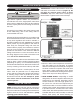
troubleshooting - Flowchart#1 ! WARNING ! Due to exposure to potentially dangerous voltages, troubleshooting should be performed by a qualified installer or service agency only. Failure to do so could result in property damage, personal injury, or loss of life. Green T-T indicator LED is on; there is a call for heat. Yes Is audible alarm sounding and red fault LED flashing? Yes (see Flowchart #3) No (See Flowchart#2) No Verify the boiler control board switch is on.
troubleshooting - flowchart#2 No (From Flowchart#1) Is the circulator indicator LED on? No Verify power supply to system. No Verify that 120vac is present at the circulator terminals. OK Verify 120vac power to Board L-N. OK Yes Verify that circulator is operating properly. No Replace the boiler control board. Yes Yes Verify circulator wiring or replace circulator. OK After 30 seconds does an element energize? No Verify that 40 amp circuit breakers are on.
(From Flowchart#1) Yes 26 Replace high limit control switches. Yes Does visual/audible alarm shut off with jumper installed? OK Remove leads from HL-HL terminals on control board and test with a jumper. OK Safety Switch Fault. Yes Is visual/audible alarm flashing/pulsing once? No No OK (See Flowchart#4) Remove leads from LWC-LWC and test with a jumper. Yes Is a low water cut-off installed? OK Remove jumper from HL-HL terminals and replace leads. Stuck/welded element relay contact.
troubleshooting - flowchart#4 A OK (From Flowchart#3) Does visual/audible alarm shut off with jumper installed? Remove jumper from LWC-LWC and replace LWC-LWC leads. No B C OK Yes Check water supply and water level in system. Fill system if low. Does visual/ audible alarm shut off with system full? Remove leads from flow-flow and test with a jumper. Yes Check pump and flow rate of system. Pump may require replacement.
homeowner's reference table Model Number:_ _____________________________________________ Serial Number:_______________________________________________ Date Installed:_ ______________________________________________ Contractor:__________________________________________________ Contact:_ ___________________________________________________ Address:____________________________________________________ ___________________________________________________________ Telephone Number:__________________________________