EG I F OPERATING AND INSTALLATION INSTRUCTIONS • ISTRUZIONI D’USO E D’INSTALLAZIONE NOTICE D’UTILISATION ET D’INSTALLATION • BEDIENUNGS-UND INSTALLATIONSANLEITUNG INSTRUCCIONES DE USO Y INSTALACION • MANUAL DE INSTRUÇÕES E INSTALAÇÃO ΟΔΗΓΙΕΣ ΧΡΗΣΗΣ ΚΑΙ ΕΓΚΑΤΑΣΤΑΣΗΣ • ANVÄNDNINGS- OCH INSTALLATIONSHANDBOK D E P GR SE Emix EMIXTank TANK200 220 V2 Emix EMIXTank TANK300 300V2 04/2017
DECLARATION OF CONFORMITY EG This product is marked as it satisfies Directives: – LVD no. 2014/35/EU (Standard: EN 60335-1:2012 + A11:2014; EN 60335-2-21:2012). – EMC no. 2014/30/EU (Standard: EN 55014-1:2006 + A1:2009 + A2:2011; EN 55014-2:1997 + A1:2001 + A2:2008; EN 61000-3-2:2014; EN 61000-3-3:2013). – RoHS2 n.2011/65/EU + 2015/863/EU amending ANNEX II. – ERP 2009/125/EC (Commission regulation EU no. 814/2013 Ecodesign Requirements). – ERP 2010/30/EU (Commission regulation EU no.
IMPORTANT! Please read before installation This system meets strict safety and operating standards. For the installer or service person, it is important to install or service the system so that it operates safely and efficiently. Recommendations • The personnel responsible for receiving the unit must conduct a visual inspection in order to identify all damage to which the unit may have been subjected during transport: refrigerating circuit, electrical cabinet, chassis and cabinet.
When connecting refrigerant tubing • Keep all tubing runs as short as possible (max. 10m), accordingly to the allowable distances from the outdoor unit (see manual). • Use the flare method for connecting tubing. • Apply refrigerant lubricant to the matching surfaces of the flare and union tubes before connecting them; screw by hand and then tighten the nut with a torque wrench for a leak-free connection. • Check carefully for leaks before starting the test run.
In addition to this, it is required: • an expansion vessel (MINIMUM 18 l) • a 3/4” water filter to be installed upstream of Emix Tank tap water connection • inlet and outlet service valves for Emix Tank • a pressure reducing valve (check hydraulic diagrams). Tools required for installation (not supplied) 1.Standard screwdriver 10.Hammer 2.Phillips head screwdriver 11.Drill 3.Knife or wire stripper 4.Tape measure 5.Level 12.Tube cutter 13.Tube flaring tool 6.Sabre saw or key hole saw 14.
MODELS COMBINATION Emix Tank must be connected to an outdoor unit compatible with Emix. For specific models see catalogue.(*) (*) The models WITHOUT EMIX PORT can not support this new device for the production of domestic hot water. This manual will use some models abbreviations of compatible outdoor units of the catalogue (Example G30 means AEI1G30EMX-GR9FI30).
TUBING LENGTH AND ELEVATION DIFFERENCE LIMITS Refrigerant Circuit Emix Tank is a component that may be connected with other indoor units at the same time by using the special connection for Emix and duly considering the length of the Emix Tank pipe to be added to the total length set by the outdoor unit (we advise a specific insulation of the Emix Tank pipes to guarantee the minimum dispersion of energy).
INSTALLATION INSTRUCTIONS A HOW TO REMOVE THE BOTTOM COVER The cover can be removed by pulling it out from the bottom. When the cover is partially removed, pull it towards you. EG B MAIN PARTS 1. 2. 3. 4. 5.
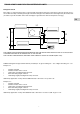
FURTHER INFORMATION C 210 200 210 260 100 260 8 15 6 482 7 4 2 84 50 9 1 3 297 5 1. SOLAR COIL INLET 2. SOLAR COIL OUTLET 3. COLD DOMESTIC WATER INLET 4. HOT WATER OUTLET 5. PRESSURE RELIEF VALVE OUTLET (6 bar) SEE NOTES BELOW 6. REFRIGERANT IN 7. REFRIGERANT OUT 8. ELECTRIC INLETS 9. SENSOR’S THERMOWELL FOR SOLAR SYSTEM 10. MAGNESIUM ANODE 11. ELECTRICAL HEATERS 12. STRATIFICATION SENSORS 13. WATER DISCHARGE + EXPANSION VESSEL CONNECTION 14. THERMOSTATIC MIXING VALVE 15.
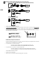
D REFRIGERANT CONNECTION BETWEEN EMIX TANK AND OUTDOOR UNIT G30 / G42 ONLY DHW (SEE SECTION “ONLY DHW APPLICATION”) R410A, 3/8” IN R410A, 3/8” OUT Emix Tank G140 EG R410A, 3/8” IN R410A, 3/8” OUT Emix Tank OTHER OUTDOOR UNITS R410A, 3/8” IN R410A, 3/8” OUT Emix Tank • • • Close the valves on the port of outdoor unit. For applications “NOT ONLY DHW”: disconnect the bypass from the valves on the Emix port (take care of it in case of removal of Emix Tank unit).
E HYDRAULIC CONNECTION BETWEEN EMIX TANK AND DOMESTIC WATER CIRCUIT • • Connect the water to the tank. Install an expansion vessel of 18 litres minimum and service valves on the connections of the water circuit in order to make installation and maintenance operations easier. The output of the safety valve should be connected to a drain. Install a filter upstream the cold water circuit and a softener (or polyphosphate treatment system) to avoid limestone.
G CONNECTION OF FLOW SWITCH ON DOMESTIC HOT WATER (OPTIONAL) FLOW SWITCH EG DHW Place the flow switch on the domestic hot water tap as shown in figure. Connect the flow switch to the connector J14 on the main board. FLOW SWITCH SPECIFICATIONS: Diameter: 3/4” Minimum flow rate: 1l/m Convention: if there is flow (tapping) the switch must be closed (dry contact).
ELECTRICAL CONNECTIONS General • The acceptable voltage variation is: ± 10% during operation. • The electrical connection conduits must be fixed. • Class 1 unit. Power supply and signal cables connection Emix Tank must always be connected to the electrical power supply in a separate manner compared to the connection of the outdoor unit, using only the bipolar shielded cable as all the other indoor units.
WIRING DIAGRAM TERMINAL BLOCKS AND ELECTRICAL CONNECTIONS EG A REMOTE CONTROL ON / OFF N L B TO OUTDOOR UNIT DELAYED FUSE Main switch for disconnection from the supply line must have a contact separation in all poles that provides full disconnection under category III overvoltage conditions. NOTE : The unit must be supplied with a dedicated electrical line. WARNING ! Always connect Phase to L and Neutral to N DO NOT INVERT THE WIRES, OTHERWISE THE CIRCULATION PUMP DOES NOT WORK PROPERLY.
LENGTH, SIZE OF WIRES AND DELAYED FUSE A B L(m) S ( mm2) L(m) S ( mm2) 15 2,5 SEE OUT.UNIT 0,75 16 A Supply power wire A: Multipolar electric wire. Size and length of the suggested electric wire are showed on table. The wire must be Mod. H07RN-F (according to CEI 20-19 CENELEC HD 22).
Flow switch connection on DHW (optional) Connect the flow switch to the connector J14. SEE SECTION G EG JUMPERS SETTING (CONTROL BOARD) FACTORY SETTING JP1 JP3 JP2 JP1= CLOSED JP2= CLOSED JP3= CLOSED (DO NOT CHANGE) JP4= OPEN (DO NOT CHANGE) JP4 WARNING ! Power down the system before changing the settings. JP1 Application type selection: CLOSED: connect the unit to the special Emix port (when Emix Tank is part of a system).
SWITCHES SETTING (CONTROL BOARD) WARNING ! Power down the system before changing the settings. SW1: SETTING OF ELECTRICAL BACKUP HEATERS See section “Setting of electrical heater elements”. EG SW3: SETTING OF TANK VOLUME Set SW3 in order to select the water volume of the tank.
HOW TO DISCONNECT AND/OR REMOVE EMIX TANK UNIT How to disconnect the refrigerant circuit In case of Emix Tank is connected to a normal indoor unit port, (for example with G30 or G42) the unit must be disconnected exactly as any other indoor unit. On the outdoor unit, electrically disconnect the reversing valve to force the system in cooling.
POWER SUPPLY Refrigerant gas tube BUS (bipolar electric shielded wire min.
POWER SUPPLY 20 Refrigerant gas tube BUS (bipolar electric shielded wire min.
8 POWER SUPPLY POWER SUPPLY POWER SUPPLY 21 Refrigerant gas tube BUS (bipolar electric POWER SUPPLY shielded wire min. 0,75 mm2) BUS (bipolar electric shielded wire min. 0,75 mm2) BUS (bipolar electric shielded wire min.
OPERATING INSTRUCTIONS Safety instructions Read this booklet carefully before using this appliance. If you still have any difficulties or problems, consult your dealer for help. This appliance is designed to give you domestic hot water. Use this only for its intended purpose as described in this Instruction Manual. WARNING ! The use of the appliance is FORBIDDEN if the tank is not filled with water. EG WARNING Never use or store gasoline or other flammable vapour or liquid near the unit.
CONTROL PANEL The control panel is located on the front of Emix Tank. From top to bottom we can see: 1 3 1...5: GREEN LED: they indicate the water temperature, both in the configuration menu (desired temperature) and in the operation menu (actual temperature). 4 6 BLUE LED: It indicates the activation of the electrical heaters. Fixed: one or more activated heaters. Flashing: BOOSTER mode selected. 7 YELLOW LED: it indicates the status of the antilegionella cycle. Fixed: active cycle.
HOW TO USE EMIX TANK When Emix Tank unit is correctly connected and electrically powered the RED LED is ON (stand by). Power ON / OFF of Emix Tank EG To switch on Emix Tank, push and hold the BUTTON for about 4 seconds until the RED LED turns off and the GREEN LEDs of water temperature light up. Emix Tank unit is designed to be always ON. To switch off Emix Tank, push and hold the BUTTON for about 4 seconds until the GREEN LEDs turn off and only the RED LED stays on. At this point release the BUTTON.
Antilegionella cycle setting To activate / deactivate the Antilegionella cycle, enter the configuration menu, then quickly press the BUTTON until the only YELLOW LED is flashing. Then wait a few seconds until all the 5 GREEN LEDs light up and press the BUTTON once more. 3 consecutive beeps confirm the setting. If the button is not pressed, after a few seconds the display will return to the main menu without making any setting. NOTE By default, the Antilegionella cycle is on.
OPERATION OF THE ELECTRICAL HEATER ELEMENTS In addition to the already described modes in the section “EMIX TANK CONFIGURATION”, Emix Tank software can automatically manage electrical back up heaters under certain conditions. This mean that these operation modes are not to be set and that can not be deactivated.
AUTO-DIAGNOSIS TABLE Error 1 3 4 5 6 8 9 10 11 12 Cause Error on outdoor unit Communication error with outdoor unit Sensor REFRIGERANT OUT damaged or disconnected Sensor H2O IN damaged or disconnected Sensor H2O OUT damaged or disconnected Electrical heaters not set Reversed refrigerant tubes error Sensor REFRIGERANT IN damaged or disconnected Tank sensor (1/3) damaged or disconnected Tank sensor (2/3) damaged or disconnected BLUE F F LED YELLOW F F RED F F F F F F F F
WIRING DIAGRAM - SCHEMA ELETTRICO - SCHÉMA ÉLECTRIQUE - SCHALTPLAN - ESQUEMA ELÉCTRICO - ESQUEMA ELÉTRICO - ΔΙΑΓΡΑΜΜΑ ΣΥΝΔΕΣΜΟΛΟΓΙΑΣ - ELSCHEMA 28
Via Alfeno Varo, 35 - 25020 Alfianello - BS - Italy Tel. +39 0331 755111 - Fax +39 0331 755501 www.argoclima.