NOTICE D’INSTALLATION INSTALLATION INSTRUCTION (Etiquette signalétique) I MANUAL DE INSTALACIÓN E AUFSTELLUNGSHANDBUCH D INSTRUÇÕES DE INSTALAÇÃO P POMPE À CHALEUR SPLIT INVERTER AIR / EAU - UNITÉ INTÉRIEURE INVERTER SPLIT AIR TO WATER HEAT PUMP - INDOOR UNIT POMPA DI CALORE SPLIT INVERTER ARIA / ACQUA - UNITÀ INTERNA BOMBA DE CALOR SPLIT INVERTER AIRE / AGUA - UNIDAD INTERIOR SPLIT INVERTER WÄRMEPUMPE LUFT/WASSER - INNENGERÄT BOMBA DE CALOR SPLIT INVERTER AIR / ÁGUA - UNIDADE INTERNA 10/2016 GB
• Do not use multi-core cable when wiring the power supply and control lines. Use separate cables for each type of line. IMPORTANT! Please read before installation This air conditioning system meets strict safety and operating standards. For the installer or service person, it is important to install or service the system so that it operates safely and efficiently. GB When transporting Be careful when picking up and moving the indoor and outdoor units.
DECLARATION OF CONFORMITY This product is marked as it satisfies Directives: – Low voltage no. 2006/95/EC. (Standard: EN60335-2-40:2003 (incl. Corr.:2006) + A11:2004 + A12:2005 + A13:2012 + A1:2006 + A2:2009 con EN 60335-1:2002 + A11:2004 + A1:2004 + A12:2006 + A2:2006 + A13:2008 + A14:2010 + A15:2011). – Electromagnetic compatibility no. 2004/108/EC, 92/31 EEC and 93/68 EEC.
1.5 - OPERATING CONDITIONS GB • Reminder: - Water system pressure: minimum: 1.5 bar, maximum: 2.5 bar. - Minimum water content (*) : 50 l (HKBE) 65 l (HKCE) 75 l (HKDE) - Maximum water content (**) : 200 l (*) If the water content of the system is below minimum, the installation of a storage tank is necessary. (*) If the water content of the system is upper maximum, the installation of an expansion tank is necessary.
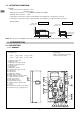
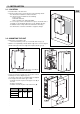
2.1.2 - ELECTRICAL BOX 1 2 3 4 5 6 7 8 9 10 11 12 - Electrical cable passage. Terminal strip. Heating element circuit breakers. Heating element contactors. Fault relay. Water flow rate relay. Circulator pump terminal. Circulator pump relay. Heating control board. Communication module CC1. Control circuit circuit-breaker. Indoor unit board. 12 9 4 11 10 8 7 6 3 5 2 1 2.1.3 - ACCESSORIES INCLUDED WITH THE APPARATUS • Hydraulic filter: • Control unit: - Plastic wall-mounted control unit.
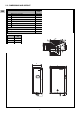
2.2 - DIMENSIONS AND WEIGHT GB HKBE-HKCE HKDE 1 Water inlet connection 3/4” male 2 Water outlet connection 3/4” male 3 Water circuit fill / drain 1/2” male 4 Safety valve connection and drainage 5 Gas refrigerant connection 1/2” flare 6 Liquid refrigerant connection 1/4” flare 7 Holes for electric cables - - A (mm) 527 B (mm) 284 C (mm) 825.5 Weight (Kg) 392 42 1 4 40.5 44 4 133.5 125 96 HKEDE 220.5 178 43 328 184 6 246 290.5 352 2 3 B A 15.
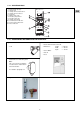
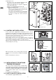
3 - INSTALLATION 3.1 - LOCATION m 1m 0.80 m 0.20 0.20 m Minimum clearance in front of the unit: 1 m • Protection index of the unit: IP 21. • Select the location for the unit on the basis of the following criteria: - the unit must be installed in a sheltered location, - the unit must not be installed near the following: . sources of heat, . combustible materials, . return / air intake of an adjacent building.
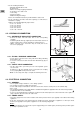
GB • Replacing the cover. - Present the cover on the unit while aligning the lower edge with the lower part of the rear support. - Fit the cover against the rear support to engage the hooks in the notches (1). - Slide the cover downward fully into place (2). - Replace the retaining screws. . Note: the screw (T) on top of the unit ensures the cover's ground continuity. This is a special screw and only this model should be used. . The screw on the left-hand side is used primarily for transport.
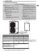
4 - CONNECTIONS 4.1 - REFRIGERATION CONNECTIONS APPLIANCES FILLED WITH R 410 A R 410 A • R 410 A is a high-pressure refrigerant (+ 50% in relation to R 22 and R 407 C). • The compressors approved for operation with this fluid are filled beforehand with polyalcohol oil. Contrary to mineral oil, it is very hygroscopic: it absorbs the humidity of the ambient air very quickly. This can modify its lubricant properties and lead in time to the destruction of the compressor.
GB • For the following information: - Maximum height between units. - Required tools. - Advice concerning the piping installation. - Connection to the outdoor unit. - Leak testing. - Vacuum operation. - Additional refrigerant charge. Refer to the installation instructions provided with the outdoor unit. • For the connection to the indoor unit's flare couplings, use 2 wrenches to maintain the coupling. Tighten to the following tightening torque values: - ø 1/4”: 14 - 18 N.m. - ø 3/8”: 34 - 42 N.m.
Note 2: The sizing of the power supply cables is to be ensured by the installer in accordance with the installation conditions and as per current standards. Cable sizes, indicated below, are given for information purposes. They are calculated in accordance with NFC 15-100 (≈ CEI 364) with the following hypotheses: - Maximum current, see table below. - Multi-pole copper cable with PR insulation. - Installation in conduit (installation method No. 3 A / 4 A / 5 A). No other power cable.
4.3.2.2 - 400 V three-phase power supply GB Single-phase power supply 400 V / 3 + N + T / 50 Hz Remove the bridges Terminal XP Indoor unit Power supply amperages and cable sizes - The sections are given as an indication only. They have to be verified and adapted, if necessary, according to the installation conditions and the standards in force.
4.3.4 - OTHER CONTROL CONNECTIONS Caution: To avoid problems related to electromagnetic disturbances, do not route these cables near power cables. GB Outside air temperature Control unit With built-in ambient temperature sensor. To be installed in zone 1. B A Load shedding (if installed) D A1 CC1 Outdoor unit C A2 Installation water return temperature Installation water outlet temperature Indoor unit E Control by pilot wire for 2nd zone (if any) with electric convectors.
GB E) Pilot wire for electric convectors (if any) - The pilot wire sends shut-down, "anti-freeze" (long term absence) or "Economy" mode instructions to the electric convectors in zone 2, and possibly in the case of 1 floor zone or 1 terminal unit zone applications. Convector control (not supplied) must be adapted to receive this type of signal (standard GIFAM 4). Consult the manual of the electric convectors. - 230 VAC signal from the heating board. - 1.
4.3.5 - ROUTING OF CABLES • • • • To avoid problems related to electromagnetic disturbances, avoid routing control cables near power cables. Pass the cables through the cable glands. Route the control cables on the right side of the electric board. Pass the pilot wire (230 V), if used, on the left side of the electric board.
GB • Water quality: - In order for the heat pump to operate under good conditions and provide optimum performance, it is essential to ensure that the system’s water circuit is clean. If the water circuit becomes clogged, this will significantly affect the machine’s performance. The circuit must therefore be cleaned with suitable products in compliance with current standards as soon as it is installed, both for new and renovation work.
6.2.3 - ZONE CONFIGURATION Set microswitch SW3 according to the application, as shown in the table.
6.3 - ADDITIONAL HYDRAULIC CIRCUIT VERIFICATIONS 6.3.1 - FORCED CIRCULATOR OPERATION GB • In order to conduct the final verifications of the hydraulic circuit, force the pump to start as follows (installation power ON): - Set the system control unit to “OFF”. N U - Temporary turn off the circuit breaker Q4. - Set microswitch SW3 of the control PCB A2 in Q4 configuration “Terminal unit or mixed zone” OFF-OFF. - Turn on the circuit breaker Q4. - Press and hold the button for 5 seconds.
6.3.4 - CIRCULATOR SPEED SETTING It is possible to select between 6 circulator curves, in two control modes: • Three proportional pressure curves (PP). • Three constant pressure curves (CP). PP1 PP2 PP3 CP3 CP2 CP1 GB FACTORY SETTING Factory setting : Constant pressure curve CP2 To change the setting: • Push the button for two seconds: Pump goes to setting mode - LEDs start flashing. • Every time you push the button, the speed setting changes: LEDs 1-2-3 flash in sequence (see the figure).
7 - MAINTENANCE INSTRUCTIONS IMPORTANT NOTE GB • Before doing any work on the installation, make sure it is switched off and all power supplies locked out. Before disconnect the outdoor unit and then the hydrokit. • Also check that the capacitors are discharged. • Any work must be carried out by personnel qualified and authorised to work on this type of machine.
7.5 - TROUBLESHOOTING RECOMMENDATIONS • All maintenance and servicing operations on the refrigerating circuit must be conducted in accordance with standard trade practices and safety rules: recovery of the refrigerant, inert shielded (nitrogen) brazing, etc… • All brazing operations must be conducted by qualified welders. • For equipment charged with R 410 A, refer to the specific instructions in paragraph 4.1 and in the outdoor unit's manual.
9 - WIRING DIAGRAM GB 22
Colours of the wires Symbols of the components A1 A2 CC1 E1 F1 F2 J1 KA1 KA2 KA3 KA4 KM1 KM2 KM3 M1 Q1 Q2 Q3 Q4 R1 R2 R3 S1 S2 S3 S4 S5 S6 BLU BLK PNK RED WHT Heating control PCB Indoor unit PCB Communication and control module Water pressostat Automatic - heater safety thermostat Manual - heater safety thermostat Water flow switch Heater fault relay Water flow relay Water flow relay Circulator pump relay R1 contactor R2 contactor R3 contactor Water circulator pump R1 circuit breaker R2 circuit breaker R
Z.I. Route départementale 28 01600 Reyrieux France Tél.