
Installation Instructions


10
GB
• For the following information:
- Maximum height between units.
- Required tools.
- Advice concerning the piping installation.
- Connection to the outdoor unit.
- Leak testing.
- Vacuum operation.
- Additional refrigerant charge.
Refer to the installation instructions provided with the outdoor unit.
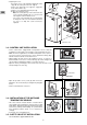
• For the connection to the indoor unit's flare couplings, use 2 wrenches to
maintain the coupling.
Tighten to the following tightening torque values:
- ø 1/4”: 14 - 18 N.m.
- ø 3/8”: 34 - 42 N.m.
- ø 1/2”: 49 - 61 N.m.
- ø 5/8”: 68 - 82 N.m.
- ø 3/4”: 100 - 120 N.m.
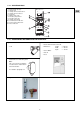
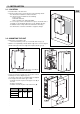
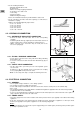
4.2 - HYDRAULIC CONNECTION
4.2.1 - WATER INLET AND OUTLET CONNECTION
• Connect the water inlet and outlet lines to the corresponding
couplings.
• Install the hydraulic filter (1) (supplied) on the water intake. Connect it
using 2 isolation valves (2) (not supplied) for cleaning purposes.
• "Water connection hose" accessories may be used (refer to the
accessories paragraph).
4.2.2 - FILLING / DRAINAGE CONNECTION
• Use the proper connection of the safety valve kit for filling or draining
water from the unit.
• To use this connection, install a shut-off valve with drain tap (3) (not
supplied).
4.2.3 - SAFETY VALVE CONNECTION
• The two safety valves open if the pressure in the hydraulic system
exceeds 3 bar.
A flexible hose (4) (not supplied) can be connected to the coupling
insert (coupling OD: 18 mm) of the two valves.
• Note: use the safety valve taps to complete the draining of the unit.
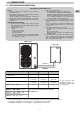
4.3 - ELECTRICAL CONNECTION
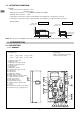
4.3.1 - GENERAL:
• The acceptable voltage variation is: ± 10% during operation.
• The electrical connection conduits must be fixed.
• Use the cable clamps underneath the unit and route the wires into the electric panel, to the terminal strips.
• Class 1 unit.
• The electrical installation must comply with the standards and regulations applicable where the unit is being installed
(in particular NF C 15-100 ≈ IEC 364).
• In case you should deactivate the hydrokit, do not disconnect the unit, but place the control unit’s knob on the symbol
(Stop), otherwise disconnect also the outdoor unit.
4.3.2 - POWER SUPPLY
• The power supply must come from an isolation and electric protection device (not supplied) in accordance with existing
regulations.
• A two-pole circuit breaker (not supplied) must be installed to protect single-phase equipment or a three-pole circuit
breaker (not supplied) for three-phase equipment. See the intensity ratings table.
Note 1
:
The unit is designed to be connected to a power supply having a TT neutral regime (neutral to ground) or TN.S regime
(to neutral) as per NF C 15-100.
1
2
3
4
4