TECHNICAL DATA & SERVICE MANUAL ARGO HPL/SCL 0.8180.612.
Table of contents Page A SPECIFICATIONS 1) Unit specifications 2) Major Component specifications 3 4 B OPERATING RANGE 6 C DIMENSIONAL DATA 7 D REFRIGERANT FLOW DIAGRAMS 8 E FUNCTIONS 1) System operation control 2) Cool Mode Operation 3) Heat Mode Operation 4) Auto Mode Operation 5) Dry Mode Operation 6) Fan Mode Operation 7) Auto Fan Speed 8) Forced Mode 9) Protection operations 10) Defrost 11) I FEEL Function 12) HI POWER mode 13) Heater resistance 14) NIGHT Function 15) LED OFF Function 16) Capac
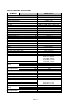
SPECIFICATIONS A 1) UNIT SPECIFICATIONS UNIT MODEL ARGO HPL/SCL Power source PERFORMANCES Capacity (air BTU / h conditioner) kW m3 / h Air circulation (high/med/low) Moisture removal (high speed) Cooling l/h ELECTRICAL RATINGS Voltage rating V Available voltage range V Running Ampere (air conditioner) A Power input (air conditioner) W Power factor C.O.
2) MAJOR COMPONENT SPECIFICATIONS UNIT MODEL ARGO HPL/SCL CONTROLLER (PCB) Part No. Controls Control circuit fuse (F1) SWITCH INDICATOR ASSY Model Led color REMOTE CONTROL UNIT THERMISTOR (ROOM SENSOR) TH1 Resistance (at 25° C) kΩ THERMISTOR (INDOOR COIL SENSOR) TH2 Resistance (at 25° C) kΩ THERMISTOR (OUTDOOR AIR SENSOR) TH3 Resistance (at 25° C) kΩ THERMISTOR (COMP.
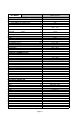
ARGO HPL/SCL UNIT MODEL COMPRESSOR (CM) Model Nominal cooling capacity oil: Freol a68ES-T or SUNICE T-68 Coil resistance (at 20° C) W cc Ω Ω Ω overload protection thermostat Rotary ( Hermetic) UG9A090FUAJP 2770 320 U-V : 2.78 V-W : 2.83 W-U : 2.73 software protection 115°C - Open °C Close °C Operating amp. (Ambient temp.
ARGO HPL/SCL UNIT MODEL CONDENSATE PUMP (PC) Model Rating Nominal intput Coil resistance (at 20° C) FLAP MOTOR (FLP) Type Model Rating Coil resistence (Ambient temp.
DIMENSIONAL DATA All dimensions are in mm C Pagina 7
D REFRIGERANT FLOW DIAGRAM ARGO HPL/SCL Pagina 8
E FUNCTIONS 1 System operation control The units receives the user input (fan speed, flap position etc) through remote controller which sends signal every time a button is pressed and in any case, automatically, every 5 minutes.
4 Auto Mode Operation In Auto Mode, the unit switches automatically between the Auto Cooling and Auto Heating in order to maintain the room temperature (RAT) at the prescribed set point (SPT).
5 Dry Mode Operation Dry operation remove moisture from indoor air running, in cooling mode, at a low level without reducing the ambient temperature. This is done cycling ON and OFF the unit according to table below.
8 Forced Mode In this mode the system operates (COOLING or HEATING mode – fixed settings) or is switched off by means of the MODE button on the pcb receiver. The operation modes can be selected pressing the button in a cyclic way (OFF COOL HEAT OFF…). The settings are: COOLING mode SET POINT temperature = 25°C FAN SPEED = HIGH FLAP POSITION = 3 HEATING mode SET POINT temperature = 21°C FAN SPEED = HIGH FLAP POSITION = 4 This special mode is useful if the remote controller is missing or unusable.
9.4 Overheat outdoor exchanger During cooling operation as soon as the outdoor coil temperature (OCT) increases, compressor speed is reduced in order to avoid heat exchanger overheating. System stops compressor operation when OCT reaches 65 °C 9.5 Compressor discharge temperature During operation, as soon as the discharge temperature increases, (CDT) compressor speed is reduced in order to avoid overheating of the motor. Compressor is stopped when CDT reaches 111°C 9.
10 Defrost The defrost process is controlled by a detection algorithm designed in order to mantain optimal utilization of the heat pump capacity especially during negative outdoor temperature conditions.
14 NIGHT Function When this setting is active indoor fan speed is automatically reduced in order to allow low noise operation.Temperature control acts in the same way as NORMAL MODE but after 60 minutes of operation the air conditioner modifies automatically the set-point temperature according to the following: •COOLING/DRY: +1°C •HEATING: - 2°C 15 LED OFF function This is a special function mode which can be selected by the user.
17 Diagnostic With this feature is possible to have a visual signal that a trouble is occurring. This mode is always active and the signalling is made through the display board LEDS . In case of no troubles the LEDS status follows its normal function.
18 Address Changing the Address of the Air Conditioner In case of more than one air conditioner operating in the same room, it may be necessary to assign an address to each unit in order to avoid operation conflicts. Address is set acting on jumpers located on the unit PCB and on dip-switches of the remote controller. The PCB settings must match the corresponding ones on the wireless remote controller How to change address of the air conditioner Dip switch is located on the battery compartment.
19 Manual Unit Control and LED indicators The push button switch and the LED indicators on display panel let the user to control the unit operation without a R/C (Remote Controller). Their operations are provided below. Push Button Switch : Use to cycle the operation mode of the A/C unit among COOL, HEAT and OFF modes, without using the R/C.
20 Drain pump Pump operates when the unit is running in COOLING and DRY modes. The level detection is done through a float switch connected at the input FS (closed under normal condition, and opened when water overflows). System operation is according to the following chart: 21 Safety thermostat The unit is equipped with a double safety system to prevent overtemperature of the electrical heater The control of temperature is done throughby the automatic thermostat (AT) and safety thermostat (ST).
F ELECTRIC WIRING DIAGRAMS ARGO HPL/SCL LEGENDA PCB FMI CM FMO RE C1-2 PC 20S EEV Controller Indoor fan motor Compressor motor Outdoor fan motor Electric heater Capacitor Condensate pump motor 4-way valve Expansion valve Pagina 20 SW-IND-ASSY TH1-2-3-4-5 ST AT EF FS FLP PR RP Indicator assy Thermistor safety thermostat automatic thermostat Emi filter Float switch Flap motor power relay pump relay
G 1 TROUBLESHOOTING CHECK BEFORE AND AFTER «TROUBLESHOOTING» (A) Check power supply wiring. • Check the power supply wires are correctly connected. (B) Check power supply. • Check that voltage is in specified range (±10% of the rating). • Check that power is being supplied. • WARNING: If the following troubleshooting must be done with power supplied, be careful not to touch any uninsulated live part that can cause electric shock 2 CIRCUIT BREAKER TRIPS OR FUSE BLOWS.
3 UNIT DOES NOT RUN. 3.1 - THERE IS NO SIGNALING LED ON UNIT Check power supply. Is power being supplied to wall receptacle? NO YES Check fuse on pcb. Is the fuse blown? The receiver assy is disconnected or defective NO YES Circuit breaker is tripped Power failure There is a possibility of short circuit Check EMI filter.
3 UNIT DOES NOT RUN. 3.2 -THERE IS ONE LED ON AT LEAST AND THE UNIT DOES NOT RECEIVES THE REMOTE CONTROL SIGNAL Check the remote controller and PCB settings for address Try with another remote controller Receiver assy may be defective PCB assy may be defective 3.
3 UNIT DOES NOT RUN. 3.4- THERE IS ONE LED BLINKING AT LEAST TEMPERATURE SENSOR DAMAGED Check sensor connection and measure its resistance Replace the sensor COMPRESSOR OVERCURRENT/ OVERTEMPERATURE OR PFC FAULT WATER LEVEL ALARM Drain the water from the service tube There is a possibility of a short circuit Measure the resistance of compressor motor windings.
4 UNIT DOES NOT RUN OR RUN FOR FEW MINUTES AND NO FAULT IS DISPLAYED Before checking the unit with this test, follow these 4 steps 1) Turn off power supply 2) Wait 1 minute until the receiver leds switch off 3) Turn on power supply 4) Wait until the system starts (about 3 minutes) Pagina 25
5 AIR CONDITIONER OPERATES, BUT ABNORMALITIES ARE OBSERVED. Is the remote controller directly under the airflow of the unit? YES Change the position of the remote controller NO Is the unit in ECO mode? YES Set the unit in HI POWER mode YES Set fan speed in medium or high speed NO Is the fan motor set in low speed? NO Check the air filter. Is it clogged? YES Clean the air filter NO Check the expansion valve coil.
6 ELECTRICAL HEATER DOES NOT WORK Before checking the unit with this test, follow these 3 steps 1) Switch the unit in FAN HEATER mode and fan on LOW speed for 3 minutes 2) Measure the power or current consumption directly from the power supply line Is the consumption much lower than the declared power input of resistance? YES Is the room temperature higher than 32°C YES Repeat the test with a temperature lower than 32°C NO Push reset button of safety thermostat and remeasure the power input.
7 AIR CONDITIONER OPERATES, BUT ABNORMALITIES ARE OBSERVED. 1 - OPERATION DOES NOT SWITCH FROM HEAT TO COOL AND FROM COOL TO HEAT Remote controller unit may be defective 8 Receiver assy may be defective Check the connection of reversing valve coil UNUSUAL NOISE IS OBSERVED Check that all the panel are fixed. Check the position of cushion rubbers under the compressor Check that internal tubes are not touching each other or with other components.
H CHECKING ELECTRICAL COMPONENTS 1 Measurement of Insulation Resistance The insulation is in good condition if the resistance exceeds 1 Mohm a) Power Supply Wires Clamp the earthed wire of the power supply wires with the lead clip of the insulation resistance tester and measure the resistance by placing a probe on either of the power wires (fig.1). Then measure the resistance between the earthed wire and the other power wires (fig.1).
Via Varese, 90 - 21013 Gallarate - Va - Italy Tel. +39 0331 755111 - Fax +39 0331 776240 www.argoclima.