
Technical data


CHECKING ELECTRICAL COMPONENTS
1
M
easuremen
t
o
f
I
nsu
l
a
ti
on
R
es
i
s
t
ance
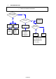
The insulation is in good condition if the resistance exceeds 1 Mohm
a) Power Supply Wires
Clamp the earthed wire of the power supply wires with the lead clip
of the insulation resistance tester and measure the resistance by placing a probe on
either of the power wires (fig.1).
Then measure the resistance between the earthed wire and the other power wires (fig.1).
b) Unit
Clamp an alluminium plate fin or copper tube with the lead clip
of the insulation resistance tester and measure the resistance by placing a probe on
N terminal, and then on Lterminal the terminal plate (fig.2)
c) Measurement of Insulation Resistance for Electrical Parts
Disconnect the lead wires of the disired electric part from terminal plate,
PCB assy, capacitor, etc.
Similary disconnect the connector. Then measure the insulation resistance (fig.1 to 4).
Refer to electric wiring diagram.
NOTE
If the probe cannot enter the poles because the hole is too narrow
then use a probe with a thinner pin.
2 Checking Continuity of fuse on PCB assy
Remove PCB assy from electrical component box (fig.5)
Then pull out the fuse from PCB assy
Check continuity of fuse by the multimeter (fig.6)
3 Checking Motor Capacitor
Remove the lead wires from the capacitor terminals, and then place a probe
on the capacitor terminals as shown in fig.7.
Observe the deflection of the pointer, setting the resistance measuring range
of the multimeter to the maximum value.
The capacitor is "good" if the pointer bounces to a great extent and
the gradually returns to its original position.
The range of deflection and deflection time deffer according
to capacity of the capacitor.
H
Pagina 29