USER and INSTALLATION MANUAL MultiSplit Air Conditioner OUTDOOR UNITS INDOOR UNITS X3MI 41 SH X3I 27 HL X3MI 56 SH X3I 35HL X3MI 61 SH X3I 52HL X3MI 71 SH X3I 64HL X3MI 80 SH Please read this manual carefully before installing and using the air conditioner, and retain for future reference.
V 03/17 34
Contents Information for use Precautions for use Description of components 3 5 Guide to the remote control and display Remote control buttons Getting to know the display icons Getting to know the remote control buttons Getting to know the button combination functions Operating guide Replacing the remote control batteries Emergency operation 6 7 7 11 12 12 14 Maintenance Care and cleaning 14 Troubleshooting Possible faults and solutions Analysing faults and solutions 15 17 Installation instructions I
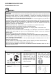
INFORMATION FOR USE Precautions for use WARNING This product is not a toy. Children of less than 3 years should be kept away unless continuously supervised. This device is not intended for persons (including children aged from 8 years and above) with reduced physical, sensory or mental capabilities, or without the necessary experience and knowledge, unless they have received the necessary supervision or instruction concerning use of the appliance by a person responsible for their safety.
Otherwise, it may overheating or fire. Otherwise, it may result in fire or electric shock. When cleaning the unit, stop operation and turn off the Interrompere l'alimentazione elettrica. power. Otherwise, may shock or damage. occur Otherwise, the accumulation of dust can cause overheating. The voltage rating of this Do not attempt to repair the air product is 220 - 240V, 50Hz. The compressor vibrates strongly if the voltage is too low, causing damage to the cooling system.
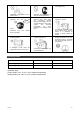
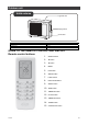
Description of components Indoor unit Unità interna ingresso aria pannellino filtro tasto ausiliario deflettore orizzontale spia spia finestrella raffreddamento alimentazione ricevitore uscita dell’aria display spia riscaldamento spia temperatura spia deumidificazione (Il contenuto o le posizioni nel display potrebbero essere diversi dalla grafica riportata qui sopra: fare riferimento al prodotto reale) Unitàinterna ingresso aria pannellino filtro tastoausiliario deflettoreorizzontale uscitadell’aria
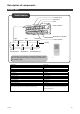
Outdoor unit Unità esterna ingresso aria impugnatura uscita aria Unitàesterna ingresso aria impugnatura uscita aria Outdoor unit air inlet handle air outlet GUIDE TO THE REMOTE CONTROL AND DISPLAY Remote control buttons V 03/17 1. ON/OFF button 2. ▲ button 3. ▼ button 4. MODE 5. FAN button 6. SWING button 7. I FEEL button 8. HEALTH/AIR button 9. SLEEP button 10. TEMP button 11. TIMER ON button 12. CLOCK button 13. TIMER OFF button 14. TURBO button 15.
Getting to know the display icons Funzione I Feel Mod. funzione Mod. Raffr. Mod. Deumi. Mod. Ventil. Mod. Riscal. Orologio Mod.Attesa Luce Funzione X‐Fan Funzione HEALTH Funzione AIR Impostazionevelocitàventola Inviosegnale Modalità turbo Funzioneriscaldamento8°C Impostazionetemperatura Impostazioneora Funzione TIMER ON/OFF Blocco bambini Inclinazione verso alto/basso Tipo Visual. Temper. Temp. Impostata Temp. Ambienteesterna Temp. Amb.
Press the ON/OFF button to turn the air conditioner on or off. When you turn on the air conditioner, the power indicator on the indoor unit's display will illuminate (green). The colour varies for different models. The indoor unit will emit a beep. 2-3. ▲/ ▼ button Press "▲" or "▼" once to increase or decrease the set temperature by 1°C. Press and hold "▲" or "▼" for 2 seconds to rapidly adjust the set temperature on the remote control.
Pressing this button will allow you to cycle through and set the fan speed: automatic (AUTO), low ( ), medium ( ) or high ( ). N.B.: When you select AUTO, the unit will automatically select the most suitable fan speed according to the factory settings. The fan will operate at low speed in dry mode. 6. SWING button Press this button to set the swing angle (up/down).
9. SLEEP button In cool, heat or dry mode, press this button to start the SLEEP function. The icon will appear on the remote control display. Press the button again to exit the SLEEP function. The icon will disappear from the display. The temperature will increase or decrease by 2 degrees over two hours according to the function selected (cool/heat). 10.
13. TIMER OFF button SETTING TIMER OFF This function allows you to program the air conditioner to turn off. When you press this button, icon will disappear from the display and the word "OFF" will flash on the remote control the display. Press "▲" or "▼" to adjust the TIMER OFF setting. Press and hold "▲" or "▼" for 2 seconds to rapidly change the time until you reach the desired value. Press "TIMER OFF". The word "OFF" will stop flashing. The icon will re-appear on the display.
N.B.: • When the 8°C heating function is enabled, the fan will operate at the default automatic speed and cannot be adjusted. The remote control will not send a signal to the unit when the TURBO button is pressed. The SLEEP and 8°C heating functions cannot operate simultaneously. If the 8°C heating function was set in cool mode, pressing the SLEEP button will cancel it. If the SLEEP function was set in cool mode, starting the 8°C heating function will cancel it.
Do not attempt to recharge the batteries. Replace both batteries at the same time. Do not throw batteries into fire; they may explode. INFORMATION FOR THE CORRECT DISPOSAL OF BATTERIES IN ACCORDANCE WITH EUROPEAN DIRECTIVE 2006/66/EC Replace batteries when they are depleted. At the end of their life, batteries must be disposed of separately from unsorted waste. They must be taken to designated recycling centres or returned to a retailer providing this service.
Emergency operation In the event of loss or failure of the remote control, use the emergency button located under the indoor unit's front panel to turn the air conditioner on or off. The unit will operate in automatic mode on start-up. pannellino pannellino tastoausiliario tasto ausiliario panel auxiliary button MAINTENANCE Care and cleaning N.B.: Disconnect the power before servicing or cleaning the unit.
Before-use checks 1. 2. 3. 4. Check that the air inlet and outlet are free of obstructions. Check that the circuit breaker, plug and socket are in good working order. Check that the filters are clean. Check that the outdoor unit's support bracket is not damaged or corroded. If it is, contact the service centre. 5. Check that the piping is not damaged. After-use checks 1. Disconnect the power supply. 2. Clean the indoor unit's panel and filters. 3.
The indoor unit's Is the indoor temperature and humidity high? air outlet produces a mist Is the unit operating in automatic mode? The set temperature cannot be adjusted Does the desired temperature fall outside the available temperature range? Is the voltage too low? The desired level Is the filter dirty? of heating/cooling Does the set temperature fall within the cannot be available temperature range? achieved Are there any doors or windows open? Is there an odour source (e.g.
Analysing faults and solutions Error codes In the event of a fault, the temperature indicator on the indoor unit will flash to display the corresponding error code. Refer to the following list to identify the error code. Error code Faults and solutions E5 Can be eliminated by turning the unit off and on again. Otherwise, contact a qualified technician for assistance. E8 Can be eliminated by turning the unit off and on again. Otherwise, contact a qualified technician for assistance.
Almeno 15 cm Distanza dal soffitto INSTALLATION INSTRUCTIONS Installation diagrams Distanza dalla parete Almeno 15 cm Almeno 15 cm z ll'o s z tru ion e Almeno 30 Distanza da Dis t Distanza dal soffitto Almeno 15 cm Distanzadallaparete Almeno 15 cm Distanzadallaparete Almeno 15 cm V 03/17 Almeno 250 cm tan a ad o Distanza dall'ostruzione Dis en cm Almeno 50 cm Alm 0 30 Distanza dal pavimento Distanza dalla parete n a nz zio sta stru i D ll'o no da me m l A c 30 e Tubo di scarico
Distanzadall’ostruzione Almeno 300 cm Distanza dal pavimento Almeno 250 cm Distanzadall’ostruzione Almeno 50 cm Distanzadall’ostruzione Almeno 30 cm Distanzadallaparete Almeno 30 cm Distanzadall’ostruzione Almeno 200 cm Tubo di scarico Distanzadall’ostruzione Almeno 50 cm Distance from obstruction At least 300 cm Distance from floor At least 250 cm Distance from obstruction At least 50 cm Distance from obstruction At least 30 cm Distance from wall At least 30 cm Distance from obstruction At least 200 cm Dr
2. The location should be well ventilated and dry; the outdoor unit must not be exposed to direct sunlight or strong winds. 3. The site should be able to support the weight of the outdoor unit. 4. Check that the installation complies with the requirements of the dimensional drawing for installation. 5. Choose a location out of the reach of children and away from animals or plants. If this is not possible, install safety fencing. Electrical connection requirements Safety precautions 1.
Indoor unit installation Decide where to install the unit based on room design, architectural limitations and customer requirements. Check that in the selected location the unit can be accessed for servicing and cleaning the filters. To install, use the installation plate as a template to identify the exact position for the wall plugs and through-hole in the wall. The plastic casing has stoppers which if necessary can be removed to route the refrigerant lines and cables.
sinistra destra sinistr posteriore destra destra posterioredestra sinistra posterioresinistra destra foro da praticare a posteriore sinistra destra foro da praticare sinistra right rear right left rear left Step five: connect the indoor unit pipe Position the pipe joint in the corresponding bellmouth. Pre-tighten the union nut by hand. right hole to be drilled left giunto tubo dado raccordo tubo giunto tubo dado raccordo pipe joint union nut Adjust the torque according to the following table.
N.B.: • Add an insulating tube to the indoor drain pipe to prevent condensation. • The plastic wall plugs are not supplied. tubo di uscita tubo di scarico nastro outlet pipe drain pipe tape Step seven: connect the indoor unit electrical cable 1. Open the panel. Remove the screw that secures the small panel covering the terminal board. pannello vite coperchio cablaggio 2. Insert the indoor and outdoor unit connecting cable into the rear hole corresponding to the terminal block.
tubo di collegamento unità interna tubo di scarico cavo di alimentazione interno ed esterno fascetta tubo gas fascetta unitàinterna cavo di alimentazione interno ed esterno tubo gas fascetta tubo di scarico tubo del liquido tubo del liquido tubo di scarico indoor unit indoor and outdoor power cable gas pipe binding tape drain pipe liquid pipe cavo di alimentazione interno tubo di collegamento tubo di scarico fascetta cavo di alimentazione interno connecting pipe drain pipe binding tape Indoor powe
Condensation produced due to the operation in heating can be piped to a drain using the appropriate predisposition. Handling the unit The handling of the product must be made by qualified and prepared personnel, who are supplied with suitable equipment made to support the weight of the product. After unpacking make sure that the content is intact and complete The outdoor unit must always be kept upright.
Use equipment and connecting pipes suitable for R410A refrigerator. MODELS Meters Pipes length with a standard refrigerating charge Maximum pipes length with additional charge Maximum pipes length per unit 10 Additional charge g/m 15 5 20 Always write the additional refrigerant charge on the data label affixed to the unit outside. The maximum height difference between indoor and outdoor unit is 10m. Wrap with straps all refrigerant pipes and joints.
cappucciovalvola pompa a vuoto chiaveesagonaleinterna chiudere aprire valve cap vacuum pump inner hex key close open Remove the piezometer. Fully open the plunger of the liquid valve and gas valve with the inner hex key. Tighten the screw caps of the valves and refrigerant charge port. Reinstall the handle. Leak detection Check for leaks using a leak detector. If you do not have a leak detector you can use soapy water.
1. Remove the cover of the terminal block on the right side of the outdoor unit. (one screw) 2. Connect the wires to the unit as shown in the figure, make sure that each cable is properly connected to the terminal boards of the two units. 3.
Post-installation checks Checks Possible fault Has the unit been installed securely? Is the thermal insulation of the pipes sufficient? The unit could fall, move or produce excessive noise. Risk of condensation and dripping water. Has the check for gas leaks been executed? Risk of cooling (heating) not satisfactory. Does the water drain properly? Risk of condensation and dripping water.
Procedure for extending the piping N.B.: Improper extension of piping is the main cause of refrigerant leaks. Proceed as shown below: 1. Cut the pipe 5. Expand the port • Check the length of the pipe based on the Expand the port using a pipe expander. distance between the indoor unit and outdoor unit. forma • Cut the required pipe using a pipe cutter. dura allargatubo tubi tubo tagliatubi inclinato irregolare sbavatura allargatubi forma dura tubo pipe expander hard mould pipe N.B.
REGULATION (EU) No. 517/2014 - F-GAS The unit contains R410A, a fluorinated greenhouse gas with global warming potential (GWP) = 2087.50. Do not release R410A into the atmosphere. X3MI 41 SH - Kg. 1,4 = 2,922 Tonn CO2 equiv. X3MI 56 SH - Kg. 1,6 = 3,34 Tonn CO2 equiv. X3MI 61 SH - Kg. 2,2 = 4,592 Tonn CO2 equiv. X3MI 71 SH - Kg. 2,2 = 4,592 Tonn CO2 equiv. X3MI 80 SH - Kg. 2,4 = 5,01 Tonn CO2 equiv. www.argoclima.