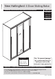
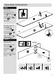
DR89959 New Hallingford -3 Door Sliding Robe Assembly Instructions- Please keep for future reference 2687249 2274463 2572048 2285665 2666387 Dimensions Width - 174,6cm Depth - 60,3cm Height -205,7cm Tip : To prevent damage, we recommend that you build your unit on the carton(s) it was packed in. Important – Please read these instructions fully before starting assembly If you need help or have damaged or missing parts, please visit: www.argos-support.co.uk or email: Help@ClickSpares.co.
Safety and Care Advice Importa – Please read these instructions fully before starting assembly Important • Check you have all the components and tools listed on pages 2 and 3. plastic bags and separate them into their groups. • Do not stand or put weight on the product, this could cause damage. • Assemble the item as close room) as possible. • Keep children and animals away from the work area, small parts could choke if swallowed.
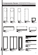
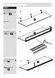
Components -Panels For damaged or missing parts, please visit: www.argos-support.co.uk or email: Help@ClickSpares.co.uk Please check you have all the panels listed below 1 Left side (205.6 x 58cm) P2350 2 Right side (205.6 x 58cm) P2350 6 Top 3 Upright (196.9 x 46.9cm) P2351 4 Slide door x2 7 Bottom (171 x 55.7cm) P1344 5 Shelf (196.3 x 58cm) P3721 (56 x 46.7cm) P1347 8 Large horizontal (171 x 55.7cm) P1345 (113.4 x 46.7cm) P1485 12 Plinth front (170.
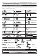
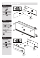
Components -Fittings For damaged or missing parts, please visit: www.argos-support.co.uk or email: Help@ClickSpares.co.uk Please check you have all the fittings listed below Note: The quantities below are the correct amount to complete the assembly. In some cases more Door-fittings FK1400 D J E Backpanelscrew x 19 (4x15mm) FK1274 FK1318 Sliding door roller adjustable x 2 Screw x 28 (3.
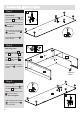
Assembly Instructions Step 1 Insert fittings a: Attach hanger rail Flip pannel F F 3 a: H H b: Attach hanger rail M support M using 12.5mm screw F Screw locking screw H into upright 3 . N M I onto upright 3 . I N M support M using 12.5mm screw F onto upright 3 . Put shelf supports N into upright 3 where shown. I 3 H F F I 3 b H 3 Note: locking screw H as far as shown. Do not over tighten.
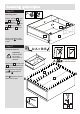
Assembly Instructions Step 3 Insert fittings a: Insert expando housings B into top 6 . B a: B B 6 Flip panel W W b: Carefully knock sliding rail W into top 6 by using a hammer. c: Insert locking screw H into top 6 . Repeat b and c for bottom 7 .
Assembly Instructions Step 4 M I Attaching panel Position top 6 upright 3 . M I I onto 6 I Insert twister cam I into upright 3 where shown. 3 8 Usa a screwdriver to turn twister cam I clockwise to lock. Temporary support Step 5 Attaching plinths A Align the sides of plinth front 12 with bottom 7 as shown and attach using chipboardscrew A Note: there are no predrilled holes for 40mm screws A A 13 7 A A Repeat with plinth back 13 .
Assembly Instructions Step 7 2 Insert fittings Attach hanger rail support M using pozi screw F onto right side. N M Screw locking screwH into right side 2 where shown. Note: Insert locking screw H as far as shown. Do not overtighten. H F H F N M H H H 2 Insert shelf supports N where shown. Step 8 M I M I Attaching panel I Position right side 2 onto top 6 and bottom 7 2 Insert twister cam I into top 6 and bottom 7 where shown.
Assembly Instructions Step 10 M I M I Attaching panel Position left side 1 onto top 6 , large horizontal 8 and bottom 7 Insert twister cam I into top 6 , large horizontal 8 and bottom 7 where shown 6 8 1 Use a screwdriver to turn locking nuts I clockwise to lock. I Step 11 A:A = B:B Fitting back panels A B B Attach back 9 and foldy back 10 to back of wardrobe with the coloured surface facing the inside of the unit using nails P and backpanelscrews D Nails P should be spaced about 150mm apart.
Assembly Instructions Step 12 Align the unit Stand up the unit Use a spirit level to check if the base of this unit is level front-to-back1, side-to-side2 and top-to-bottom 3 in the three positions shown. 3 1 2 Use pegs S to level your unit in all three direction shown. Knock peg S in, as far as you require,under the ends of the unit and then snap off peg flush with the panel.
Assembly Instructions Step 113 Insert shelf Position shelf 5 onto shelf supports N and fix by screwing four chipsboardscrews O through shelf supports N into shelf 5 5 b: 5 N O Step 14 Inserting hanger rails Place hanger rails U and V onto hanger rail supports M.
Assembly Instructions GLASS handle with care Step 15 K Insert fittings Q K Stick felts Q onto mirror slide door 11 where shown. Insert Slidingdoor rollers L in mirror slide door 11 on the side which is flush with the handle mouldings T . Insert slidingdoor guides K on the other end of the mirror slide door 11 .
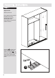
Assembly Instructions Step 18 K See page 2 for link to instruction video! Insert fittings K Insert Sliding door rollers L in slide doors 4 on the side of the handle mouldings T on the end which is flush with the handle mouldings T . This will be the Right Hand Door Insert sliding door roller adjustables J in slide door flush 4 on the other side, fix them with backpannel screws D L D D J Insert sliding door guides K on the other end of the slide door 4 .
Assembly Instructions Step 20 See page 2 for link to instruction video! Insert fittings C Screw expanding dowel C into plinth top 14 . C 14 C Step 21 14 B Attaching plinth Position the plinth top 14 above the unit and slot expanding dowels C into the expando housing B The top of the plinth top 14 must be flush with the top of the unit. Turn the screws in the expando housings B as far as they will go.
Assembly Instructions Step 23 Attaching L-bracket X Position L-Bracket G onto top 6 as shown, fix by using 15mm screw D G D 6 Note: there are no pre-drilled holes for 15mm screw D . Use X to fix on the wall, please see last page for more information. X Step 24 R Attaching door-stops Stick 2 door-stops R onto the outside edge of each plain door to act as buffers between the doors and side panels.
Assembly Instructions If your doors do not run smoothly Level & square the unit Level & square the unit up: Knock the pegs S as far as you require, under the ends of the unit and then snap off flush with the panel. For more detailed information see step 12. Raise the door To raise the door, loosen the screws and swivel the glide towards the ‘+’ arrow. Re-tighten the screws. Lower the door To lower the door, loosen thescrews and swivel the glide towards the ‘-’ arrow. Re-tighten the screws.
A Guide to - Wall Mounting & Fixings Important note: If plastic wall plugs are supplied with your product: Important: When drilling into walls always check that there are no hidden wires or pipes etc. Make sure that the screws and wall plugs being used are suitable for supporting your unit. Consult a qualified tradesperson if you are unsure. Hints: - these are only suitable for use in masonry walls. If you are in any doubt about the correct wall plugs for your wall, seek professional advice.