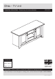
Ohio - TV Unit Assembly Instructions - Please keep for future reference 309/6561 Dimensions Width - 120cm Depth - 39.5cm Height - 61.
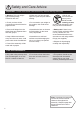
Safety and Care Advice Important - Please read these instructions fully before starting assembly • Warning: This unit weighs approximately 30kgs. Please lift with care. • Make sure you have enough space to layout the parts before starting. • Check you have all the components and tools listed on pages 2 and 3. • Do not stand or put weight on the product, this could cause damage. • Remove all fittings from the plastic bags and separate them into their groups.
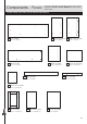
Components - Panels If you have damaged or missing components, call the Customer Helpline: 08456 400800 quoting the reference numbers below Please check you have all the panels listed below 1 Top (D1782A) 2 Left Side (D1783A) (1200 x 395mm) (590 x 357mm) 4 Base (D1785A) 5 Divider (D1786A) (480 x 349mm) x 2 (1020 x 350mm) 8 Plinth (D1789A) 3 Right Side (D1784A) (590 x 357mm) 6 Large Shelf (D1787A) (444 x 348mm) x 2 9 Fascia (D1790A) (590 x 70mm) x 2 (1020 x 95mm) 7 Small Shelf (D1788A) (271 x
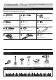
Components - Fittings If you have damaged or missing components, call the Customer Helpline: 08456 400800 quoting the reference numbers below Please check you have all the fittings listed below Note: The quantities below are the correct amount to complete the assembly. In some cases more fittings may be supplied than are required.
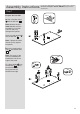
Assembly Instructions If you have damaged or missing components, call the Customer Helpline: 08456 400800 quoting the reference numbers below Step 1 Prepare the left side 10mm A B a: Tap a wooden dowel .A into the left side 2 . Note: Wooden dowels must not stick out from the edge by more than 10mm or they may damage other panels. Screw 3 metal dowels B into the left side 2 . A B B B a: 2 Note: Tighten the metal dowels up fully against the panels.
Assembly Instructions Step 2 A B Prepare the right side a: Tap a wooden dowel .A into the right side 3 . B B a: 3 Screw 3 metal dowels B into the right side 3 . b: Insert 4 large locking C nuts C into the right side 3 . Fit 2 hinge plates J onto the right side 3 , making sure that the slot is facing towards the finished front edge.
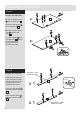
Assembly Instructions Step 4 Join the left side to the left fascia panel a: C a: Push the left side 2 down onto the left fascia panel 9 . 2 B Dowel this end Left fascia b: b: Use a screwdriver to tighten the 2 large locking nuts C fitted to the left side 2 . Note: Turn the large locking nuts C as far as they will go - more than 1/2 a turn. 9 C 2 9 Step 5 Join the right side to the right fascia panel a: Push the right side 3 down onto the right fascia panel 9 .
Assembly Instructions Step 6 Prepare the base C C Insert 4 large locking nuts C into the base 4 . in la p C d ar o b ip ch 4 a rf su C ce Finished front edge Step 7 Fit the base 3 Push the base 4 onto the right side 3 . Use a screwdriver to tighten the 2 large locking nuts C fitted to the base 4 . pla 4 in c hip bo ard sur Finished front edge C Step 8 Prepare the 2 dividers Insert 2 large locking nuts C into each of the 2 dividers 5 .
Assembly Instructions Step 9 Finished front edge Fit the dividers 5 Attach the 2 dividers 5 to the base 4 using 4 screws G . Note: To make it easier to fit the 2 dividers, place polystyrene blocks from the packaging underneath to raise them up level. 5 G 4 G G Finished front edge G Polystyrene block C Step 10 A Prepare the plinth in la p Tap 2 wooden dowels A into the plinth 8 . ip ch C d ar o b Insert 2 large locking nuts C into the plinth 8 .
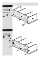
Assembly Instructions Step 12 Fit the left side Push the left side 2 onto the assembly. Use a screwdriver to tighten the 3 large locking nuts C fitted to the base 4 and plinth .8 . 4 2 8 Step 13 Fit the 5 plastic nails Tap 2 plastic nails L into the bottom edge of each of the sides 2 and .3 . The other plastic nail L taps into the the bottom edge of the plinth . 8 .
Assembly Instructions Step 14 B Prepare the top Screw 8 metal dowels B into the top 1 . B B B B B B 1 B Finished front edge Step 15 Fit the top Carefully stand the unit up for this step. Warning: The unit is heavy. Lift with care. Push the top 1 down onto the assembly. 1 3 Use a screwdriver to tighten the 8 large locking nuts C fitted to the left side 2 , the right side 3 and the 2 dividers 5 .
Assembly Instructions Step 16 a: The measurement from top corner X to bottom corner X must be equal to the measurement from top corner Y to bottom corner Y Fit the backs b: Lay the unit back down for this step. x E a: Square up the unit by making sure that measurement x to x equals y to y. y 12 c: 11 E b: Place the 2 small backs .11 . onto the unit. Nail E around the outside edges of the small backs 11 . 11 c: Place the large back .12 .
Assembly Instructions Step 17 Fit the shelves Make sure that the plastic sleeve is fully pushed onto the shelf stud. H Insert 4 shelf studs H for each shelf at the required height. Lower the large shelves . 6 and small shelves 7 down onto the shelf studs H . H x4 H x8 7 6 H x4 6 7 Step 18 F F Prepare the 2 doors F Push fit 2 hinges K into each of the 2 doors 10 . 10 K Secure each hinge with 2 screws F .
Assembly Instructions Step 19 Drill 2 handle holes in each of the doors IMPORTANT Carefully choose which 2 holes you need to drill in each door Important: Please follow these instructions carefully. ONLY drill these 2 holes in 1 door Lay the 2 doors 10 down onto a smooth surface. Check that the hinges and holes are in the same place as the diagrams. Note: We recommend the use of a small piece of waste wood, placed behind the holes while drilling, to reduce the possibility of any breakout.
Assembly Instructions Step 20 Fit doors and handles a: J b: J K K Note: The easiest way to attach each door 10 is to fit the top hinge first, then align and fit the other hinges. a: Push the hinge K onto the front part of the hinge plate J . The recess at the bottom of screw B goes into the slot in the hinge plate. b: Keep the hinge A B c: K d: J J J K K B K FLAT against the hinge plate J as you slide it across as far as it will go. Tighten screw A.
Assembly Instructions Step 21 Adjust the doors if needed a: a: Before adjusting the doors, use a spirit level to check the base (or top) of the unit is level, front-to-back and side-to-side in the 3 positions shown. Use suitable packing pieces (not supplied) to make the unit level BEFORE making any adjustment to the hinges, as shown. b: A A b: Height adjustment. Loosen screws A on hinge plates and move door up or down as required. Retighten screw A. c: B c: Forward and Back adjustment.