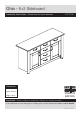
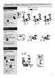
Ohio - 6+2 Sideboard Assembly Instructions - Please keep for future reference 314/7128 Dimensions Width - 120cm Depth - 39.
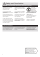
Safety and Care Advice Important - Please read these instructions fully before starting assembly • Warning: This unit weighs approximately 43kgs. Please lift with care. • Make sure you have enough space to layout the parts before starting. • Check you have all the components and tools listed on pages 2 and 3. • Do not stand or put weight on the product, this could cause damage. • Remove all fittings from the plastic bags and separate them into their groups.
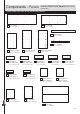
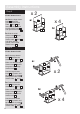
Components - Panels If you have damaged or missing components, call the Customer Helpline: 03456 400800 quoting the reference numbers below Please check you have all the panels listed below 1 Top (D1811A) 2 Base (D1814B) (1200 x 395mm) (1016 x 350mm) 6 Plinth (D1816A) (1016 x 95mm) 7 Fascia (D1806A) (755 x 70mm) x 2 3 Divider (D1815B) (645 x 349mm) x 2 4 Left Side (D1812B) (755 x 357mm) 8 Left Drawer 9 Right Drawer Side (W350-124LH) Side (W350-124RH) (350 x 124mm) x 6 (350 x 124mm) x 6 (342 x 162
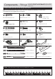
Components - Fittings If you have damaged or missing components, call the Customer Helpline: 03456 400800 quoting the reference numbers below Please check you have all the fittings listed below Note: The quantities below are the correct amount to complete the assembly. In some cases more fittings may be supplied than are required.
Assembly Instructions If you have damaged or missing components, call the Customer Helpline: 03456 400800 quoting the reference Step 1 Note: The left drawer front 10 has a shallow identification mark. numbers below Prepare the drawer fronts Screw 2 metal dowels B into the holes shown on the left drawer front 10 , the right drawer front 11 and the 4 central drawer fronts 12 . B B B B B 10 B 11 x1 Note: Tighten metal dowels up fully against the panels.
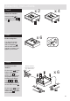
Assembly Instructions Step 4 Fit the drawer bases a: Slide the large drawer base 15 down the grooves in the drawer sides 8 and 9 and down into the groove in the left drawer front 10 and right drawer front 11 . x2 a: x4 15 9 8 b: 10 11 16 9 b: Slide the small 8 drawer base 16 down the grooves in the drawer sides 8 and 9 and down into the groove in the central drawer fronts 12 . 12 Step 5 Fit the drawer backs a: Fit the large drawer back 13 between the drawer sides 8 and 9 .
Assembly Instructions x2 Step 6 Attach the handles Attach a handle O to each drawer front 10 , 11 and 12 using 2 screws H . H x4 H H H O 10 12 O 11 Step 7 Fit the wedgefixes x6 I I Turn all of the drawer assemblies over and slide 2 wedgefixes I into the front and back grooves, as shown, and tighten up the screws.
Assembly Instructions Step 9 Prepare the 2 fascias Check that the holes are in the same place as the diagrams, as one will be the left fascia and one will be the right fascia. B Left fascia - holes nearest this side 10mm A B B B B 7 Screw 3 metal dowels B into each of the 2 fascias .7 . Tap a wooden dowel A into each of the 2 fascias .7 . x1 7 x1 Prepare the left side C Insert 3 large locking nuts C into the left side .4 .
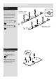
Assembly Instructions a: Step 11 Join the left side to the left fascia panel C 4 a: Push the left side 4 down onto the left fascia panel 7 . B Dowel this end Left fascia b: b: Use a screwdriver to tighten the 3 large locking nuts C fitted to the left side 4 . C 4 Note: Turn the large locking nuts C as far as they will go - more than 1/2 a turn. 7 Step 12 C Prepare the right side Insert 3 large locking nuts C into the right side 5 .
Assembly Instructions Step 13 Join the right side to the right fascia panel a: a: Push the right side 5 down onto the right fascia panel 7 . 5 C Dowel this end B Right fascia 7 b: Use a screwdriver to tighten the 3 large locking nuts C fitted to the right side 5 . Note: Turn the large locking nuts C as far as they will go - more than 1/2 a turn.
Assembly Instructions Step 14 a: Fit a runner P a to the left side 4 . Finished front edge Finish preparing the left side 1st screw J 2nd screw J 3rd screw J P a The 1st screw J uses the 1st hole in from the front of the runner. J B B B The 2nd and 3rd screws .J use the holes that line up with the other panel holes. J J P a a: 4 Screw 3 metal dowels B into the left side 4 . b: Fit a screw K into the 1st hole in at the top of the runner P a .
Assembly Instructions Step 15 J Finish preparing the right side 3rd J 2nd screw screw J 1st screw P b a: Fit a runner P b to the right side 5 . The 1st screw J uses the 1st hole in from the front of the runner. The 2nd and 3rd screws .J use the holes that line up with the other panel holes. J B B J J B a: P b 5 Screw 3 metal dowels B into the right side 5 . b: Fit a screw K into the 1st hole in at the top of the runner P b . Insert 2 large locking nuts C into the right side 5 .
Assembly Instructions Step 17 Fit the base Push the base 2 onto the right side 5 . 5 Use a screwdriver to tighten the 2 large locking nuts C fitted to the base 2 . pla 2 in c hip bo ard sur fac e Finished front edge Step 18 Prepare the plinth A in la p Tap 2 wooden dowels A into the plinth 6 . C C ch d ar o b ip Insert 2 large locking nuts C into the plinth 6 . e ac rf su 6 A Step 19 Fit the plinth 5 Push the plinth 6 onto the right side 5 .
Assembly Instructions Step 20 Fit the left side Push the left side 4 onto the assembly. 2 Use a screwdriver to tighten the 3 large locking nuts C fitted to the base 2 and plinth .6 . 4 6 Step 21 Fit the 5 plastic nails Tap 2 plastic nails L into the bottom edge of each of the sides 4 and . 5 and 1 into the centre of the bottom edge of the plinth 6 . 5 L L 4 6 L L L Step 22 Prepare the top Screw 8 metal dowels B into the top 1 .
Assembly Instructions Step 23 Prepare the left divider J 3rd J 2nd screw screw J 1st screw P b K a: Fit a runner P b to the divider 3 . P b The 1st screw J uses the 1sthole in from the front of the runner. a: The 2nd and 3rd screws . J use the holes that line up with the other panel holes. J J J b: P b 3 Finished front edge b: Fit a screw K into the 2nd hole in at the top of the runner P b . K 3 A Finished front edge A Tap 2 wooden dowels A into the divider 3 .
Assembly Instructions Step 24 3rd screw J 2nd screw J 1st screw P b a: The 2nd and 3rd screws . J use the holes that line up with the other panel holes. P b a: The 1st screw J uses the 1st hole in from the front of the runner. J J J K Finished front edge Fit 4 runners P b to the divider 3 . Finished front edge Prepare the right divider J J J J J J J J J P b J 3 b: P b P b P b b: K Finished front edge Fit a screw K into the 2nd hole in at the top of the runner P b .
Assembly Instructions Step 25 Fit the dividers Carefully stand the unit up for this step. 3 Push the 2 dividers 3 down onto the base 2 . 3 Warning: The unit is heavy. Lift with care. 2 Finished front edge Step 26 Fit the top Push the top 1 down onto the assembly. Finished front edge 1 Use a screwdriver to tighten the 8 large locking nuts C fitted to the left side 4 , the right side 5 and the 2 dividers 3 .
Assembly Instructions Step 27 a: The measurement from top corner X to bottom corner X must be equal to the measurement from top corner Y to bottom corner Y Fit the back x Lay the unit back down for this step. a: Square up the unit by making sure that measurement x to x equals y to y. b: Place the back b: E y 19 y 19 onto the unit. Nail E around the outside edges of the back 19 . Note: Nails should be spaced about 150mm apart. x Warning: The unit is heavy. Lift with care.
Assembly Instructions Step 29 Fit the drawers Note: The left drawer front has a small identification hole. Please refer back to Step 1. Slide the wheels of the runners fitted to the drawers, over the wheels of the runners fitted to the side panels and push the drawers into position. Drawer Step 30 Fit the shelf studs Insert the shelf studs F . You have a choice of 3 height positions. F x4 F x4 Make sure that the plastic sleeve is fully pushed onto the shelf stud.
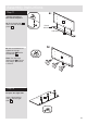
Assembly Instructions Step 31 Fit the shelves Lower the 2 shelves 17 down onto the shelf studs F . 17 17 Step 32 K Prepare the 2 doors K Push fit 2 hinges N into each of the 2 doors 18 . 19 K 18 N Secure each hinge with 2 screws K . Note: Before securing with the screws, make sure that the hinges are positioned at 90 degrees with the edge of the door.
Assembly Instructions Step 33 Drill 2 handle holes in each of the doors Important: Please follow these instructions carefully. IMPORTANT Carefully choose which 2 holes you need to drill in each door ONLY drill these 2 holes in 1 door Lay the 2 doors 18 down onto a smooth surface. Check that the hinges and holes are in the same place as the diagrams. Note: We recommend the use of a small piece of waste wood, placed behind the holes while drilling, to reduce the possibility of any breakout.
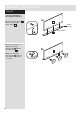
Assembly Instructions Step 34 Fit doors and handles a: M b: M N N A Note: The easiest way to attach each door 18 is to fit the top hinge first, then align and fit the other hinges. a: Push the hinge N onto the front part of the hinge plate M . The recess at the bottom of screw B goes into the slot in the hinge plate. b: Keep the hinge B c: M N d: M M N N B N FLAT against the hinge plate M as you slide it across as far as it will go. Tighten screw A.
Assembly Instructions Step 35 Adjust the doors if needed a: a: Before adjusting the doors, use a spirit level to check the base (or top) of the unit is level, front-to-back and side-to-side in the 3 positions shown. Use suitable packing pieces (not supplied) to make the unit level BEFORE making any adjustment to the hinges, as shown. b: A A b: Height adjustment. Loosen screws A on hinge plates and move door up or down as required. Retighten screw A. c: B c: Forward and Back adjustment.
Assembly Instructions Step 36 Assembly is complete Warning: The unit is heavy. Lift with care. If you need help or have damaged or missing parts, call the Customer Helpline: 03456 400800 and quote the reference numbers on the component pages.