2 Burner Gas BBQ with side burner Assembly Instructions - Please keep for future reference 345/0901 307223 Dimensions Width - 112cm Depth - 52cm Height - 96.5cm Important - Please read this instructions fully before using the appliance If you need help or have damaged or missing parts, call the Customer Helpline: 03456 400800 (Argos)/ 03450 778888 (Homebase). Please visit the website www.argos.co.uk or www.homebase.co.uk for more information.
Safety and Care Advice Important - Please read this instructions fully before using the appliance • • • • • • • • • • • • • • • • • • • • • • • • • • • • • • Assembly time: approx. 45 mins. Retain these instructions for future reference. Use outdoors only. Do not use the barbecue or store gas bottles below ground level. LP gas is heavier than air so if a leak occurs the gas will collect at a low level and could ignite in the presence of a flame or spark. For use with LPG bottled gas only.
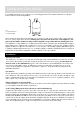
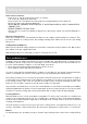
Safety and Care Advice For optimal performance, we suggest to use a 5-15kg gas bottle. The maximum dimension of the gas bottle is dia 31.5cm and height 58cm. 2 Key 1= maximum diameter 2= maximum height 1 Never mount the gas bottle under the barbecue on the base shelf as this could result in serious injury to the user, other people and/or property. Always place the gas bottle at the side of the appliance. The gas bottle should be sited as far away from the appliance as possible without straining the hose.
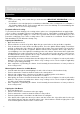
Safety and Care Advice Operation Warning • Before proceeding, make certain that you understand the IMPORTANT INFORMATION section of this manual. • Your barbecue is not designed to be used with more than 50% of the cooking area as a solid plate — this includes baking dishes. Full coverage will cause excessive build-up of heat and damage the barbecue. This is not covered by warranty.
Safety and Care Advice Manual Ignition Instruction for Side Burner • Set the control knob to the off position. • Apply a lit match on the gap to burner ports. • Push and turn the control knob anti-clockwise to max position and the burner should ignite. If the burner fails to ignite, contact your local dealer for assistance. Grill Cooking The burners heat up the flame tamer underneath the grill, which in turn heats the food on the grill.
Safety and Care Advice In the event of a fat fire: ‧ If safe to do so, turn all control knobs to the ‘off’ position. ‧ Turn off the gas supply at the gas bottle. ‧ Keep everyone at a safe distance from the barbecue and wait until the fire has burnt out. ‧ Do not close the hood or lid of the barbecue. ‧ NEVER DOUSE A BARBECUE WITH WATER. IF AN EXTINGUISHER IS USED, IT SHOULD BE A POWDER TYPE. ‧ DO NOT REMOVE THE DRIP TRAY.
Safety and Care Advice the burners clean. The burners should be removed and cleaned annually, or whenever heavy build-up is found, to ensure that there are no signs of blockage (debris, insects) in either the burner portholes or the primary air inlet of the burners. Use a pipe cleaner to clear obstructions. When refitting the burners, be careful to check that the neck of the burner fits over the valve outlet. It is quite normal for surface rust to be present on the burners.
Safety and Care Advice Fixings All screws and bolts, etc. should be checked and tightened on a regular basis. Storage Ensure the barbecue is properly cooled before covering or storing. Store your barbecue in a cool dry place. It must be inspected on a regular basis as damp or condensation can form which may result in damage to the barbecue. It may be necessary to dry the barbecue and the inside of the cover if used. Mould can grow under these conditions and should be cleaned and treated if required.
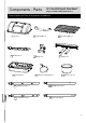
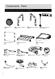
Components - Parts If you have damaged or missing components, call the Customer Helpline: 03456 400800 (Argos)/ 03450 778888 (Homebase).
Components - Parts Please check you have all the panels listed below 14 Wheel x 2 15 Left upper support x1 18 Front canvas x1 21 Side table front support x1 25 Side burner electrode x 1 9 19 Bottom shelf x1 22 Side table rear support x1 26 Side burner x 1 16 Right upper support x1 17 Control panel assembly x 1 20 Side table x1 23 Side burner assembly x1 27 Side burner grate x 1 24 Side burner knob x 1 28 Venturi clip x1
Components - Fittings Please check you have all the panels listed below Note: The quantities below are the correct amount to complete the assembly.
Assembly Instructions Step 1 Fix the left front leg 12 and left rear leg 13 on the bot19 using 12mm tom shelf bolts B . F3 F2 13 12 19 B B B B F11 FRONT Step 2 Fix the right front leg 10 and left rear leg 11 on the bottom shelf 19 using 12mm bolts B .
Assembly Instructions Step 3 Install the wheels 14 to the left front leg 12 and left rear leg 13 using the axles J . 13 12 Then fix the axles J by R pins L . J 14 L L F10 14 F9 FRONT F8 J Step 4 Connect the left upper sup15 with the left front port leg 12 and left rear leg 13 using 20mm bolts A and M6 nuts F . Repeat the same connection of the right upper support 16 with the right front leg 10 and right rear leg 11 using 20mm bolts A and M6 nuts F .
Assembly Instructions Step 5 Fix the control panel assem17 on the left upbly 15 and right per support upper support 16 using 12mm bolts B . 15 16 17 F7 B B FRONT Step 6 Fix the heat tent support K on the firebowl 7 using 8mm bolts I and M4 nuts D .
Assembly Instructions Step 7 Set the firebowl 7 on the left upper support 15 and right upper support 16 using 20mm bolts A . 7 A7 A A A A B6 15 B7 16 Step 8 a: Put the burner 6 a: 66 through the hole of the fire7 . bowl b: Align all valves on the control panel assembly 17 against each venturi of the burner 6 . Important: Make sure the valve tip goes into the venturi tube completely with good alignment. Fix the burner 6 on the fire7 using 10mm bowl screws C .
Assembly Instructions Step 9 Fix the hinge 5 on the fire7 using 8mm bolts bowl G and M5 nuts M . A5 5 G 5 G M 7 M Step 10 Put the washer E between the lid handle 2 and the lid 1 . Align the holes and fix the lid handle 2 on the lid 1 usG .
Assembly Instructions Step 11 Fix the lid 1 and firebowl 7 by the hinge 5 using 8mm bolts G and M5 nuts M . 1 M 5 M G 5 G 7 Step 12 Assemble the side table front support 21 and the side table rear support 22 to the side table 20 . C C E1 Secure the supports with 10mm screws C .
Assembly Instructions Step 13 Install the side table assembly made on step 12 to the right upper support by 16 H . 15mm shoulder bolts 20 H H H H 16 Step 14 Install the side burner assembly 23 to the left up15 using per support B 12mm bolts .
Assembly Instructions Step 15 a: Loosen the preassembled screws on the side burner valve of the con17 . trol panel assembly b: Fix the side burner valve on the side burner panel bracket of the side burner assembly 23 using the screws. c: Put the side burner 26 and the side burner elec25 through the trode hole of side burner assembly 23 .
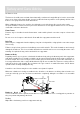
Assembly Instructions Step 15 d: d: Align the venturi of the side burner valve. 26 against the Important: Make sure the valve tip goes into the venturi tube completely with good alignment. I Then tighten the side burner on the side burner assembly using 8mm bolt I . 26 Burner venturi Connect the electrode of the main burner 6 and the side burner electrode 25 to the electrode end of ignitor on the control panel assembly 17 .
Assembly Instructions Step 15 f: Insert the hook end of the venturi clip 28 into the air hole of the side burner venturi. Then clip another end on the side burner valve. f: The venturi clip is used to stabilize the side burner so as to make sure the side burner valve tip goes into the burner venturi securely with the right position.
Assembly Instructions Step 16 Put the grease cup hanger 8 through the hole of the firebowl 7 . B6 8 7 8 8 Side view Top view Step 17 Hang the grease cup 9 on the grease cup hanger 8 . Attach the front canvas 18 to the left front leg 12 and right front leg 10 . Secure the position with the velcro on canvas edge.
Assembly Instructions Step 18 Put the side burner knob 24 on the side burner assembly 23 . B1 3 Put the heat tent 4 and cooking grill 3 on the fire7 . bowl B2 4 23 7 24 Step 19 Assembly is complete. ALL JOINTS AND CONNECTIONS MUST NOW BE LEAK TESTED BEFORE USING THE BARBECUE. Leak test annually, and whenever the gas bottle is removed or replaced. Always place the gas bottle at the side of the appliance.
Technical Specification Model Number KS0993 Gas Category I3+(28-30/37) Type of Gas Propane Gas Pressure 37 mbar Pin Number 28 - 30 mbar 359/BU/1015 Injector Size (Main Burner) 0.75mm Injector Size (Side Burner) 0.74mm Total Heat Input 7.0 kW 2 Burner Heat Input 4.7 kW Side Burner Heat Input 2.3 kW Gas Consumption 500 g/h Country of Destination GB and IE Do not use this barbecue outside England and Ireland.
Troubleshooting Problem Possible Cause Burner will not light LP gas cylinder is empty using the ignition sysFaulty regulator tem Obstructions in burner Obstructions in gas jets or gas hose Solution Replace with full cylinder Have regulator checked or replace Clean burner Clean jets and gas hose Electrode wire is loose or disconnected Reconnect wire on electrode or ignition unit.