Kensington - 3 Drawer 2 Door Robe Assembly Instructions - Please keep for future reference 414/6946 4111335 Dimensions Width - 85.9cm Depth - 49.5cm Height - 198.8cm MADE IN BRITAIN Important - Please read these instructions fully before starting assembly If you need help or have damaged or missing parts, please visit www.argos-support.co.uk or email: Help@ClickSpares.co.uk (quoting your original order number) Alternatively, call the Spares Helpline on: 0370 112 1928.
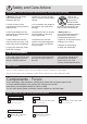
Safety and Care Advice Important - Please read these instructions fully before starting assembly • Warning: This unit weighs approximately 59kgs. Please lift with care. • Make sure you have enough space to layout the parts before starting. • Check you have all the components and tools listed on pages 2 and 3. • Do not stand or put weight on the product, this could cause damage. • Remove all fittings from the plastic bags and separate them into their groups.
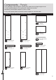
Components - Panels If you need help or have damaged or missing parts, please visit www.argos-support.co.uk or email: Help@ClickSpares.co.uk (quoting your original order number) Alternatively, call the Spares Helpline on: 0370 112 1928. For any other queries please contact the Customer Helpline on: 0345 640 2020 Please check you have all the panels listed below 8 Top (DF2409) (85.9 x 49.5cm) 9 Shelf (DF2413) (79.7 x 47.4cm) 10 Hanging Rail (FHR791) 6 Left Side (DF2410) (197.3 x 47.
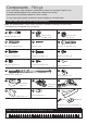
Components - Fittings If you need help or have damaged or missing parts, please visit www.argos-support.co.uk or email: Help@ClickSpares.co.uk (quoting your original order number) Alternatively, call the Spares Helpline on: 0370 112 1928. For any other queries please contact the Customer Helpline on: 0345 640 2020 Please check you have all the fittings listed below Note: The quantities below are the correct amount to complete the assembly. In some cases more fittings may be supplied than are required.
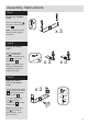
Assembly Instructions Step 1 A Prepare the 3 drawer fronts A A Screw 2 metal dowels A into each of the 3 drawer fronts 1 . 1 x3 Note: Tighten the metal dowels up fully against the panels. Step 2 Prepare the drawer sides C Insert a small locking nut C into the hole shown on the left drawer side 2 and the right drawer side 3 . C C 3 2 x3 Note: The arrow on the locking nut must point towards the hole in the edge of the panel.
Assembly Instructions Step 4 Fit the drawer base 5 Slide the drawer base 5 down the grooves in the drawer sides 2 and 3 and down into the groove in the drawer front 1 . 2 3 x3 1 Step 5 Fit the drawer back Fit the drawer back 4 between the drawer sides 2 and 3 . Make sure that the drawer base 5 fits into the groove in the drawer back 4 . F F 3 4 5 F F Hold the drawer back 4 in position and tap the knock-in pegs F through the holes in the drawer sides 2 and 3 .
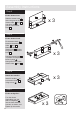
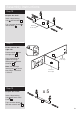
Assembly Instructions Step 8 P J Prepare the left side M P a: Place 3 runners M on the left side 6 as shown. Slide back the top of runner and use the 2nd hole from the front to fit the 1st screw J . Fit 3 hinge plates P onto the left side 6 , making sure that the slot is facing towards the finished front edge. Finished front edge P P J J a: 6 J M M M b: Slide the runners M back the other way and fit the 2nd screw J into the corresponding holes in the left side 6 .
Assembly Instructions Step 9 J Prepare the right side P M a: Place 3 runners M on the right side 7 as shown. Slide back the top of runner and use the 2nd hole from the front to fit the 1st screw J . P P a: 7 J J J Fit 3 hinge plates P onto the right side 7 , making sure that the slot is facing towards the finished front edge. M M M b: Slide the runners M back the other way and fit the 2nd screw J into the corresponding holes in the right side 7 .
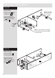
Assembly Instructions Step 10 Prepare the shelf B D D B B Insert 4 large locking nuts B into the shelf 9 . B 9 Tap 4 wooden dowels D into the shelf 9 . Finished front edge D D Step 11 A Fit the shelf to the right side B Push the shelf 9 onto the right side 7 . 7 Use a screwdriver to tighten the 2 large locking nuts B fitted to the shelf 9 . Finished front edge 9 Note: Turn the large locking nuts B as far as they will go - more than 1/2 a turn.
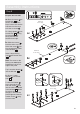
Assembly Instructions Step 13 Fit the 5 rails Note: The holes for this rail must be on this side Push the 5 rails 11 onto the right side 7 . 7 Use a screwdriver to tighten the large locking nut B fitted to each of the 5 rails 11 . 11 11 11 11 11 Note: Fit this rail last and support it until the left side has been fitted in the next step. Step 14 Fit the left side Push the left side 6 onto the assembly. Use a screwdriver to tighten the 2 large locking nuts B fitted to the shelf 9 and the 5 rails 11 .
Assembly Instructions Step 15 Prepare the top A A A Screw 4 metal dowels A into the top 8 . A 8 Step 16 Fit the top Note: To make it easier to fit the top and plinths, place polystyrene blocks from the packaging underneath the side panels to raise the assembly. Warning: The unit is heavy. Lift with care. Polystyrene block Polystyrene block 8 Push the top 8 onto the assembly. Polystyrene block Use a screwdriver to tighten the 4 large locking nuts B fitted to the sides 6 and 7 .
Assembly Instructions Step 18 a: Fit the back The measurement from top corner X to bottom corner X must be equal to the measurement from top corner Y to bottom corner Y a: Square up the unit by making sure that measurement x to x equals y to y. b: Place the back x b: y E 16 onto the unit. 16 Nail E around the outside edges of the back 16 . y Note: Nails should be spaced about 150mm apart.
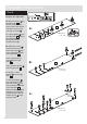
Assembly Instructions Step 20 Finished top edge B Prepare a side plinth Insert a large locking nut B into 1 of the side plinths 13 . 13 D Tap a wooden dowel D into the side plinth 13 . Step 21 Prepare the other side plinth B D Finished top edge Insert a large locking nut B into the side plinth .13 . 13 Tap a wooden dowel D into the side plinth 13 . Step 22 A Prepare the front plinth Profiled top edge Screw 2 metal dowels A into the front plinth 12 .
Assembly Instructions Step 24 Fit the plinths Position the 3 plinths around the outside of the assembly, ensuring that the bottom edge of the plinths are flush with the bottom edge of the sides, as shown. 13 Secure the 2 side plinths 13 through the left end 6 and right end 7 using screws G . 7 G G G G 13 6 13 Carefully stand the unit up for the next step. Warning: The unit is heavy. Lift with care.
Assembly Instructions Step 26 Fit the hanging rail and shelf studs 10 Push the hanging rail 10 into the rail holders O fitted to the side panels. 10 O Push the 2 shelf studs S down into the holes in the shelf 9 to act as door buffers. S Step 27 S K K Prepare the 2 doors K Push fit 3 hinges Q into each of the 2 doors 14 and 15 . Secure each hinge with 2 screws K . Note: Before securing with the screws, make sure that the hinges are positioned at 90 degrees with the edge of the door.
Assembly Instructions Step 28 a: P Fit doors and handles Q A onto the front part of the hinge plate P . The recess at the bottom of screw B goes into the slot in the hinge plate. b: Keep the hinge B c: P Q Q Note: The easiest way to attach each door 14 and .15 is to fit the top hinge first, then align and fit the other hinges. a: Push the hinge b: P Q d: P P Q Q B Q FLAT against the hinge plate P as you slide it across as far as it will go. Tighten screw A.
Assembly Instructions Step 29 Adjust the doors if needed a: a: Before adjusting the doors, use a spirit level to check the base (or top) of the unit is level, front-to-back and side-to-side in the 3 positions shown. Use suitable packing pieces (not supplied) to make the unit level BEFORE making any adjustment to the hinges, as shown. b: A A b: Height adjustment. Loosen screws A on hinge plates and move door up or down as required. Retighten screw A. c: B c: Forward and Back adjustment.
Assembly Instructions Step 30 Strap T Washer Strap F Screw (not supplied) U N IT Washer O Wall fixing (not supplied) Screw T P To prevent possible overbalancing we recommend that this unit is secured to a suitable wall by fitting of the overbalance protector kit .T to the unit, or an alternative fixing method of your choice. L L WA TO Fit the overbalance protector T Wall fixings are not supplied as they will need to suit the wall type.
ALR3177