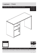
Lawson - Desk Assembly Instructions - Please keep for future reference 402/4439 412/6416 412/3392 Dimensions Width - 100cm Depth - 39.5cm Height - 73.
Safety and Care Advice Important - Please read these instructions fully before starting assembly • Warning: This unit weighs approximately 20kgs. Please lift with care. • Make sure you have enough space to layout the parts before starting. • Check you have all the components and tools listed on pages 2 and 3. • Do not stand or put weight on the product, this could cause damage. • Remove all fittings from the plastic bags and separate them into their groups.
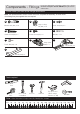
Components - Panels If you have damaged or missing components, call the Customer Helpline: 03456 400800 quoting the reference numbers below Please check you have all the panels listed below 1 Left End (DF2766) (716 x 392mm) 2 Upright (DF2767) (716 x 392mm) 4 Top (DF2765) 3 Right End (DF2768) (716 x 392mm) 5 Base (DF2769) (996 x 396mm) (327 x 390mm) x2 6 Shelf (DF2770) (327 x 373mm) 7 Modesty (DF2772) (620 x 157mm) 8 Door (DF2771) (326 x 321mm) 9 Back (X707-353) (707 x 353mm) 2
Components - Fittings If you have damaged or missing components, call the Customer Helpline: 03456 400800 quoting the reference numbers below Please check you have all the fittings listed below Note: The quantities below are the correct amount to complete the assembly. In some cases more fittings may be supplied than are required.
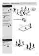
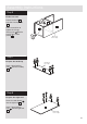
If you have damaged or missing components, call the Customer Helpline: 03456 400800 quoting the reference Assembly Instructions numbers below Step 1 B Prepare the upright Screw 4 metal dowels A into the upright 2 . A A B A A Note: Tighten the metal dowels up fully against the panels. 2 Finished front edge Insert 2 large locking nuts B into the upright .2 . Note: The arrow on the locking nut must point towards the hole in the edge of the panel.
Assembly Instructions Step 3 A Fit a base to the upright B Push a base 5 onto the upright 2 . 2 5 Use a screwdriver to tighten the 2 large locking nuts B fitted to the upright 2 . Finished front edge Finished front edge Note: Turn the large locking nuts B as far as they will go - more than 1/2 a turn. Step 4 Fit the other base to the upright 2 Push the base 5 onto the upright 2 . 5 Use a screwdriver to tighten the 2 large locking nuts B fitted to the upright 2 .
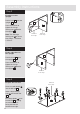
Assembly Instructions Step 6 Fit the left end Push the left end 1 onto the 2 base panels .5 . 5 1 Use a screwdriver to tighten the 2 large locking nuts B fitted to each of the 2 base panels 5 . Step 7 5 Finished front edge B B Prepare the modesty Insert 4 large locking nuts B into the modesty .7 . Step 8 Finished top edge B B 7 A A B Prepare the right end B Screw 2 metal dowels A into the right end 3 . Insert 2 large locking nuts B into the right end .3 .
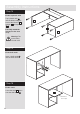
Assembly Instructions Step 9 Finished top edge Fit the modesty 7 Push the modesty 7 onto the upright 2 . Use a screwdriver to tighten the 2 large locking nuts B fitted to the modesty 7 . 2 Note: Support the modesty until the right end has been fitted in the next step. Step 10 Fit the right end Push the right end 3 onto the modesty 7 . 7 Use a screwdriver to tighten the 2 large locking nuts B fitted to the modesty 7 .
Assembly Instructions Step 12 Fit the ltop 4 Push the top 4 onto the assembly. 3 Use a screwdriver to tighten the 6 large locking nuts B fitted to left end 1 , upright 2 and right end 3 . 2 1 Step 13 Fit the back a: a: Square up the unit by The measurement from top corner X to bottom corner X must be equal to the measurement from top corner Y to bottom corner Y making sure that measurement x to x equals y to y. b: Place the back b: 9 F onto the unit.
Assembly Instructions Step 14 Fit the 6 plastic nails Tap 2 plastic nails G into the bottom edge of each of the left end 1 , upright 2 and right end .3 . Carefully stand the unit up for the next step. Warning: The unit is heavy. Lift with care. G G 3 G 2 G 1 G G Step 15 Fit 4 shelf studs Insert 4 shelf studs C into the holes shown. C x4 Step 16 Fit the shelf Lower the shelf 6 down onto the shelf studs C .
Assembly Instructions Step 17 Fit the door stop Push the remaining shelf stud C up into the hole in the corner of the upper base 5 to act as a door stop. 5 C Step 18 E Prepare the door Push fit 2 hinges I into the door 8 . Secure each hinge with 2 screws E . Note: Before securing with the screws, make sure that the hinges are positioned at 90 degrees with the edge of the door.
Assembly Instructions Step 19 a: Fit door and handle H I onto the front part of the hinge plate H . The recess at the bottom of screw B goes into the slot in the hinge plate. b: Keep the hinge H I I A Note: The easiest way to attach the door 8 is to fit the top hinge first, then align and fit the other hinge. a: Push the hinge b: H I c: B d: H I H I B I FLAT against the hinge plate H as you slide it across as far as it will go. Tighten screw A.
Assembly Instructions Step 20 Adjust the door if needed a: a: Before adjusting the door, use a spirit level to check the top (or base) of the unit is level, frontto-back and side-to-side in the 3 positions shown. Use suitable packing pieces (not supplied) to make the unit level BEFORE making any adjustment to the hinges, as shown. b: A A b: Height adjustment. Loosen screws A on hinge plates and move door up or down as required. Retighten screw A. c: B c: Forward and Back adjustment.
Assembly Instructions Step 21 Assembly is complete If you need help or have damaged or missing parts, call the Customer Helpline: 03456 400800 and quote the reference numbers on the component pages.
ALR3189