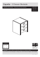
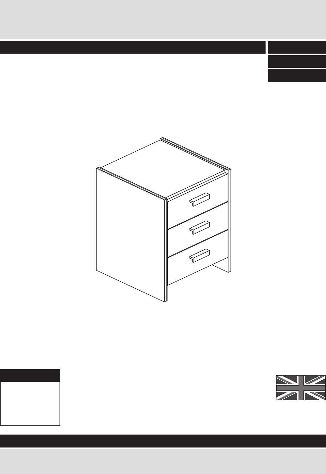
Capella - 3 Drawer Bedside Assembly Instructions - Please keep for future reference 395/8056 424/5263 408/6192 Dimensions Width - 38cm Depth - 39cm Height - 58.
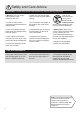
Safety and Care Advice Important - Please read these instructions fully before starting assembly • Warning: This unit weighs approximately 13kgs. Please lift with care. • Make sure you have enough space to layout the parts before starting. • Check you have all the components and tools listed on pages 2 and 3. • Do not stand or put weight on the product, this could cause damage. • Remove all fittings from the plastic bags and separate them into their groups.
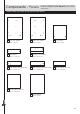
Components - Panels If you have damaged or missing components, call the Customer Helpline: 03456 400800 quoting the reference numbers below Please check you have all the panels listed below 1 Left Side (D1006A) 2 Right Side (D1007A) 4 Rail (D1002A) 5 Drawer Front (D1003A) (345 x 157mm) x 3 (584 x 390mm) (349 x 103mm) x2 6 Left Drawer Side (W370-124LH) (370 x 124mm) x 3 (584 x 390mm) 7 Right Drawer Side (W370-124RH) (370 x 124mm) x 3 3 Top (D1001A) (349 x 370mm) 8 Drawer Back (W317-124) (317 x
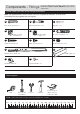
Components - Fittings If you have damaged or missing components, call the Customer Helpline: 08456 400800 quoting the reference numbers below Please check you have all the fittings listed below Note: The quantities below are the correct amount to complete the assembly. In some cases more fittings may be supplied than are required.
Assembly Instructions If you have damaged or missing components, call the Customer Helpline: 03456 400800 quoting the reference numbers below Step 1 B Prepare the 3 drawer fronts Screw 2 metal dowels B into each of the drawer fronts 5 . B B 5 Note: Tighten the metal dowels up fully against the panels. x3 Step 2 Prepare the drawer sides Insert a small locking nut E into the hole shown on the left drawer side 6 and the right drawer side 7 .
Assembly Instructions Step 4 Fit the drawer base 9 Slide the drawer base 9 down the grooves in the drawer sides 6 and 7 and down into the groove in the drawer front 5 . x3 7 6 5 Step 5 Fit the drawer back Fit the drawer back 8 between the drawer sides 6 and 7 . Make sure that the drawer base 9 fits into the groove in the drawer back 8 . F F 8 x3 7 F 9 F 6 Hold the drawer back 8 in position and tap the knock-in pegs F through the holes in the drawer sides 6 and 7 .
Assembly Instructions Prepare the left side a: Profiled front edge Step 8 Place 3 runners J on the left side 1 . Slide back the top of the runner and use the 1st hole from the front to fit the 1st screw I . b: Slide the runner back the other way and fit the 2nd screw I into the corresponding hole in the left side 1 . I J I Profiled front edge I I a: J J J 1 c: Screw 4 metal dowels B into the left side 1 .
Assembly Instructions Step 9 J Prepare the right side Place 3 runners J on the right side 2 . Slide back the top of the runner and use the 1st hole from the front to fit the 1st screw I . I J a: I J 2 Profiled front edge I b: Slide the runner back the other way and fit the 2nd screw I into the corresponding hole in the right side 2 . J c: Screw 4 metal dowels B into the right side 2 .
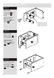
Assembly Instructions Step 10 D A Prepare the top Tap 4 wooden dowels A into the top 3 as shown. D D A D 3 Note: Wooden dowels must not stick out from the edge by more than 10mm or they may damage other panels. Finished front edge A A D A Insert 4 large locking nuts D into the top 3 as shown. 10mm Note: The arrow on the locking nut must point towards the hole in the edge of the panel. Step 11 B Fit the top to the right side D Push the top 3 onto the right side 2 as shown.
Assembly Instructions Step 13 Fit the 2 rails 2 Push the rails 4 onto the right side 2 as shown. 4 Use a screwdriver to tighten the 2 large locking nuts D fitted to the rails 4 . 4 Support this rail until the left side has been fitted in the next step. Step 14 Fit the left side 3 Push the left side 1 onto the assembly. 4 Use a screwdriver to tighten the 4 large locking nuts D fitted to the top 3 and the rails 4 .
Assembly Instructions Step 16 a: Fit the back a: Square up the unit by making sure that measurement x to x equals y to y. b: Place the back The measurement from top corner X to bottom corner X must be equal to the measurement from top corner Y to bottom corner Y b: x C 10 onto the unit. Nail C around the outside edges of the back 10 . Note: Nails should be spaced about 150mm apart. y 10 y x Stand the unit up for the next step.
Assembly Instructions Step 18 Assembly is complete If you need help or have damaged or missing parts, call the Customer Helpline: 03456 400800 and quote the reference numbers on the component pages.