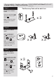
Kensington - Dressing Table & Stool Assembly Instructions - Please keep for future reference 411/5290 428/7070 Dresser Dimensions Stool Dimensions Width - 119.9cm Width - 43cm Depth - 39.4cm Depth - 35.5cm Height - 76.1cm Height - 48cm MADE IN BRITAIN Important - Please read these instructions fully before starting assembly If you need help or have damaged or missing parts, please visit www.argos-support.co.uk or email: Help@ClickSpares.co.
Safety and Care Advice Important - Please read these instructions fully before starting assembly • Warning: This unit weighs approximately 37kgs. Please lift with care. • Make sure you have enough space to layout the parts before starting. • Check you have all the components and tools listed on pages 2 and 3. • Do not stand or put weight on the product, this could cause damage. • Remove all fittings from the plastic bags and separate them into their groups.
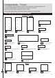
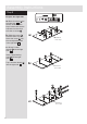
Components - Panels If you need help or have damaged or missing parts, please visit www.argos-support.co.uk or email: Help@ClickSpares.co.uk (quoting your original order number) Alternatively, call the Spares Helpline on: 0370 112 1928. For any other queries please contact the Customer Helpline on: 0345 640 2020 Please check you have all the panels listed below Dressing Table 4 Modesty (DF3473) (69.1 x 21.5cm) x 2 1 Left Side (DF4477) (74.6 x 37.4cm) 2 Right Side (DF2405) 3 Fly End (DF3472) (74.
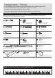
Components - Fittings If you need help or have damaged or missing parts, please visit www.argos-support.co.uk or email: Help@ClickSpares.co.uk (quoting your original order number) Alternatively, call the Spares Helpline on: 0370 112 1928. For any other queries please contact the Customer Helpline on: 0345 640 2020 Please check you have all the fittings listed below Note: The quantities below are the correct amount to complete the assembly. In some cases more fittings may be supplied than are required.
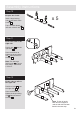
Assembly Instructions Step 1 If you have damaged or missing components, call the Customer Helpline: 03456 400800 quoting the reference numbers below The Dressing Table will be built first Prepare the 3 drawer fronts Screw 2 metal dowels A into each of the drawer fronts 9 . A A A x3 9 Note: Tighten the metal dowels up fully against the panels. Step 2 Prepare the drawer sides Insert a small locking nut C into the hole shown on the left drawer side 10 and the right drawer side 11 .
Assembly Instructions Step 4 Fit the drawer base Slide the drawer base 13 down the grooves in the drawer sides 10 and 11 and down into the groove in the drawer front 9 . 13 x3 11 10 9 Step 5 Fit the drawer back Fit the drawer back 12 between the drawer sides 10 and 11 . Make sure that the drawer base 13 fits into the groove in the drawer back 12 . Hold the drawer back 12 in position and tap the knock-in pegs E through the holes in the drawer sides 10 and 11 .
Assembly Instructions Step 8 J Prepare the left side M a: Place 3 runners M on the left side 1 as shown. Slide back the top of runner and use the 2nd hole from the front to fit the 1st screw J . b: Slide the runner M back the other way and fit the 2nd screw J into the corresponding hole in the left side 1 . Finished front edge J J J M 1 M a: M Finished front edge J J c: Screw 5 metal dowels A into the left side 1 . J b: 1 Insert 2 large locking nuts B into the left side .1 .
Assembly Instructions Step 9 J Prepare the right side M a: Place 3 runners M on the right side 2 as shown. Slide back the top of runner and use the 2nd hole from the front to fit the 1st screw J . b: Slide the runner M back the other way and fit the 2nd screw J into the corresponding hole in the right side 2 . J J 2 a: J M M M Finished front edge c: Screw 5 metal dowels A into the right side 2 . J Insert 2 large locking nuts B into the right side 2 .
Assembly Instructions Step 10 Prepare the 5 rails B D B Insert 2 large locking nuts B into each of the 5 rails 5 . x5 5 Tap 2 wooden dowels D into each of the 5 rails 5 . Step 11 Fit 3 of the rails to the right side D A B Push 3 rails 5 onto the right side 2 . 2 Use a screwdriver to tighten the large locking nut B fitted to each of the rails 5 . 5 5 5 Note: Turn the large locking nuts B as far as they will go - more than 1/2 a turn.
Assembly Instructions Step 13 Fit the left side Push the left side 1 onto the rails 5 . 5 5 5 Use a screwdriver to tighten the large locking nut B fitted to each of the rails 5 . 1 5 5 Step 14 Fit the 4 plastic nails Tap 2 plastic nails L into the bottom edge of each of the sides 1 and .2 . L 2 L 1 L L Step 15 Prepare a side plinth B Insert a large locking nut B into 1 of the side plinths 7 . Finished top edge 7 Tap a wooden dowel D into the side plinth 7 .
Assembly Instructions Step 17 A Prepare the front plinth A Screw 2 metal dowels A into the front plinth 6 . 6 Step 18 Finished top edge Fit the plinths together Push the 2 side plinths 7 onto the front plinth 6 . Profiled top edge 7 6 Note: To make it easier to fit the top and plinths, place polystyrene blocks from the packaging underneath both side panels to raise the assembly.
Assembly Instructions Step 20 B B x2 Prepare the 2 modesty panels Insert 4 large locking nuts B into each of the 2 modesty panels 4 . B B 4 Finished front edge Step 21 A Prepare the fly end Screw 4 metal dowels A into the fly end 3 . Insert 2 large locking nuts B into the fly end .3 . B D A Finished front edge A B A D 3 Tap 2 wooden dowels D into the fly end 3 . Step 22 Fit the 2 modesty panels Push the 2 modesty panels 4 onto the left side 1 .
Assembly Instructions Step 23 Note: Place 2 more polystyrene blocks from the packaging underneath the fly end. Fit the fly end Push the fly end 3 onto the 2 modest panels 4 . Use a screwdriver to tighten the 2 large locking nuts B fitted to each modesty 4 . 4 4 Tap 2 plastic nails L into the bottom edge of the fly end 3 . 3 L Polystyrene block L Step 24 Polystyrene block A A Prepare the top Screw 6 metal dowels A into the top 8 .
Assembly Instructions Step 25 Fit the top Push the top 8 onto the assembly. 2 Use a screwdriver to tighten the 2 large locking nuts B fitted to each of the sides 1 and . 2 and the fly end 3 . 8 1 3 Step 26 a: Fit the back The measurement from top corner X to bottom corner X must be equal to the measurement from top corner Y to bottom corner Y a: Square up the unit by making sure that measurement x to x equals y to y. b: Place the back b: x N 14 onto the unit.
Assembly Instructions Step 27 I Fit the drawers Starting with the bottom drawer, slide both the runners M forward and locate the drawer sides 10 and 11 between them, lining up the holes in the drawer wrap with the 2nd 'threaded' holes in the runners M . Working from the inside of the drawer, insert 2 screws I through the drawer sides and out into the 2nd threaded hole in the runner. M 2nd threaded hole I I 11 10 Note: Do not overtighten the screws I .
Assembly Instructions Step 28 B x6 Prepare the 2 stool sides Screw 6 metal dowels B into each of the 2 stool sides 15 , as shown. x2 15 Step 29 B Prepare the stool base D B B Insert 4 large locking nuts B into the holes in the stool base 16 . B 16 Tap 2 wooden dowels D into the ends of the stool base 16 . D Step 30 Fit a stool side to the stool base 16 Fit one of the stool sides 15 to the stool base 16 . Use a screwdriver to tighten the 2 large locking nuts B fitted to the stool base 16 .
Assembly Instructions Step 32 Fit the 2 stool rails Push the 2 stool rails 17 down onto the stool side .15 , as shown. 17 17 Use a screwdriver to tighten the 2 large locking nuts B fitted to each stool rail 17 . Step 33 15 a: Fit the other stool side 15 16 a: Push the other stool side 15 down onto the assembly, as shown. Use a screwdriver to tighten the 2 large locking nuts B fitted to the stool base 16 .
Assembly Instructions Step 34 Fit the seat pad Position the seat pad 18 onto the assembly and make sure that its 4 edges line up with the stool base 16 . Hold the seat pad 18 in position and screw up through the 4 holes in the stool base 16 using screws F . 18 F F 16 Soft surface F F Hard surface Note: Make sure that you screw into the hard surface of the seat pad. Step 35 Fit the plastic nails Tap 2 plastic nails L into the bottom edge of each of the stool sides 15 as shown.
Assembly Instructions Step 36 O Strap O Screw Washer Strap Washer IT Wall fixing (not supplied) Attach the strap to the unit N To prevent possible overbalancing we recommend that the dressing table is secured to a suitable wall by fitting of the overbalance protector kit O to the unit, or an alternative fixing method of your choice.
ALR3181