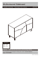
Multicoloured Sideboard Assembly Instructions - 453/4785 Please keep for future reference - Dimensions Width - 120cm Depth - 42cm Height - 74cm Important - Please read these instructions fully before starting assembly If you need help or have damaged or missing parts, call the Customer Helpline: Argos = 0345 6400800 Version 1 Date: 22/09/15
Safety and Care Advice Important – Please read these instructions fully before starting assembly • Check you have all the components and tools listed on the following pages. • During assembly do not stand or put weight on the product, this could cause damage. • Remove all fittings from the plastic bags and separate them into their groups. • Assemble the item as close to its final position (in the same room) as possible.
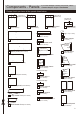
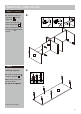
Components - Panels If you have damaged or missing components, call the Customer Helpline: Argos = 0345 6400800 Please check you have all the panels listed below Pilot holes for guidance only Pilot holes for guidance only Pilot holes for guidance only 1 Left panel (39.9 x 55.6cm) 2 Right panel 3 Middle right panel (39.9 x 55.6cm) (39.9 x 55.6cm) 12 Large drawer back 4 Middle panel (39.8 x 17.4cm) 20 Leg x 4 (7 x 15cm) (66.6 x 14.5cm) 21 Bottom support 5 Top panel (120.
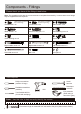
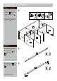
Components - Fittings Please check you have all the fittings listed below Note: The quantities below are the correct amount to complete the assembly. In some cases more fittings may be supplied than are required.
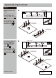
Assembly Instructions Step 1 Attaching runners and hinges a: 2 Holes upside 2 4 A A A a: Position the Left out- J side runners J in from front edge of the Left panel 2 and Middle panel 2 . J A Use Screws A to fix the Left outside runners J onto the Left panel 2 and Middle panel 4 . A A J 2 Pilot holes for runner position 4 2 A A Pilot holes for runner position J A 4 b: Position the Right out- side runners L in from front edge of the Right panel 1 and Middle right panel 3 .
Assembly Instructions Step 1 - continued c: Screw Locking pins into the Left panel 2 . E c: E Note: Insert locking pins E as far as shown. Do not over tighten. B E Use Screws B to fix the Door hinges I ‘back plates’ onto the Left panel 2 . H B I Insert Dowels H into the Left panel 2 and Middle panel 4 . I 2 I H H d: Screw Locking pins E into the Right panel 1 . B d: 4 E E Note: Insert locking pins as far as shown. Do not over tighten.
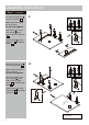
Assembly Instructions Step 2 Attaching the middle shelf panel a: H a: Use Screws C to fix Left shelf 7 onto the Middle panel 4 . 7 Insert Dowels H into the Left shelf 7 . 4 C C b: Use Screws C to fix Middle right panel the Left shelf 7 . 3 onto b: 7 C 3 C c: Use Screws to fix Right shelf 8 onto the Middle right panel 3 . C c: C Insert Dowels H into the Right shelf 8 . 7 C 3 8 H Continued on next page.
Assembly Instructions Step 2 - continued d: Use Screws C to fix Middle left panel 9 onto the Left shelf 7 . d: C 7 C 9 3 8 Step 3 Attaching the left and right panel a: F a: Carefully locate the Right panel 1 onto the Left shelf 7 . Insert 2 Locking nuts into the Left shelf 7 . F Use a screwdriver to turn Locking nuts F clockwise to lock. F 1 7 F Continued on next page.
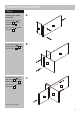
Assembly Instructions Step 3 - continued b: b: Carefully locate the Left panel 2 onto the Right shelf 8 . F Insert 2 Locking nuts F into the Right shelf 8 . Use a screwdriver to turn Locking nuts F clockwise to lock. 8 F 2 F Step 4 a: Attaching top panel a: Screw Locking pins into the Top panel 5 . E E E Note: Insert locking pins E as far as shown. Do not over tighten. E E E 5 E Continued on next page.
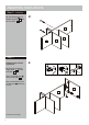
Assembly Instructions Step 4 - continued b: Carefully locate the Top panel 5 onto the unit. Insert 6 Locking nuts into the unit. b: F F Use a screwdriver to turn Locking nuts F clockwise to lock. F 5 1 F F F 3 F F 2 Step 5 Attaching bottom panel a: H a: Insert Dowels H into the Front bottom panel 19 . 19 H b: Position Legs 20 onto the Front bottom panel 19 . 19 20 9 20 b: Continued on next page.
Assembly Instructions Step 5 - continued c: Use 14 Screws C to fix Front bottom panel 19 , Legs 20 and Bottom support 21 onto the Bottom panel 6 . c: C C C C C C 20 C 19 20 C C 6 20 21 19 20 d: Use 8 Screws Bottom panel unit.
Assembly Instructions Step 6 N Fixing back panels Unfinished back surface Attach Small back panel 26 and Large back panel 25 using nails N . 25 Important: The unit MUST be ‘square’ when back is attached. 26 Step 7 a: Drawer assembly a: Screw Locking pins E E into the Large drawer front 10 and Small drawer front 11 . E Note: Insert locking pins as far as shown. Do not over tighten. E E 10 11 E E E Continued on next page.
Assembly Instructions Step 7 - continued b: Fix Drawer right 17 , Drawer left 16 and Drawer support 18 on to Large drawer front 10 and Small drawer front 11 . Insert 9 Locking nuts into the Drawer right Drawer left 16 and Drawer support 18 . G 17 b: G , 16 Use a screwdriver to turn Locking nuts G clockwise to lock. G 16 18 17 17 10 11 G G G c: Carefully slide the Large drawer bottom 14 and Small drawer bottom 15 into the grooves.
Assembly Instructions Step 7 - continued e: Use Screws A to fix the Left inside runners M and Right inside runners K onto the unit. e: A A K A M A 14 A A A 10 A M A A K A A 15 11 Step 8 Inserting drawers With help, carefully stand unit upright. Warning: The unit is heavy. Lift with care. Slide the assembled drawers fully onto runners.
Assembly Instructions Step 9 Fix 6 Door hinges I to Left door panel 22 , Middle door panel 23 and Right door panel 24 using Screws B . B B Attaching hinges to doors B B B I I I O 22 I I 23 B Tear off the protective backing from the Door Pads O . O O B I Carefully stick the Door pads O onto the Left door panel 22 , Middle door panel 23 and Right door panel 24 . I 24 O Step 10 Hanging doors a: With help, slot Door hinges plates’.
Assembly Instructions Step 11 Hinge adjustment a: To move doors up or a: down: loosen screws shown and move doors to suit. Once doors are aligned, re-tighten Screws B . b: To move doors in or out: loosen screw shown and move doors to suit. Door b: Re-tighten screws. Door c: To move doors left or right: loosen screw shown and move doors to suit. c: Re-tighten screws.
Assembly Instructions Step 12 Finishing the unit Note: It would be useful to ask someone to help you at this stage. With help, place the unit in the intended position. Assembly is complete.