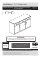
Anderson - 3+3 Sideboard Assembly Instructions - Important: Retain these instructions for future reference 609/6465 609/6458 WARNING! In order to prevent overturning, this product must be used with the 2 wall attachment devices provided Dimensions Width - 119.
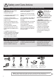
Safety and Care Advice Important - Please read these instructions fully before starting assembly • Warning: This unit weighs approximately 42kgs. Please lift with care. • Parts of the assembly will be easier with 2 people. • Assembly to be carried out by a competent adult only. • Make sure you have enough space to layout the parts before starting. • Check you have all the components and tools listed on pages 2 and 3. • Do not stand or put weight on the product, this could cause damage.
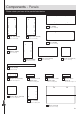
Components - Panels Please check you have all the panels listed below 3 Top (D2266A) (119.3 x 39.6cm) 1 Left Side (D2182A) 2 Right Side (D2183A) (74.7 x 37.5cm) (74.7 x 37.5cm) 4 Base (D2268A) (115.4 x 37.4cm) 5 Divider (D2260A) (15 x 37.4cm) 8 Small Shelf (D2271A) 7 Large Shelf (D2261A) 6 Upright (D2267A) (37.1 x 36.8cm) (76.2 x 36.8cm) (67.15 x 37.4cm) 9 Plinth (D2269A) (115.4 x 6cm) 10 Drawer Front (D2263C) (39 x 15.5cm) x 3 11 Left Drawer Side (WD330-115LH) (33 x 11.
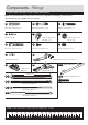
Components - Fittings Please check you have all the fittings listed below Note: The quantities below are the correct amount to complete the assembly. In some cases more fittings may be supplied than are required.
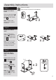
Assembly Instructions Step 1 Drawer Assembly www.youtube.com/watch?v=3fYL5zB6ZYQ Prepare the drawer fronts B B Screw 2 metal dowels B into the holes shown on the back of each drawer front 10 . B 10 Note: Tighten metal dowels up fully against the panels. x3 Step 2 Prepare the drawer sides Insert a small locking cam nut F into the hole shown on the left drawer side 11 and right drawer side 12 .
Assembly Instructions Step 4 Fit the drawer base Slide the drawer base 14 down the grooves in the drawer sides 11 and 12 and down into the groove in the drawer front 10 . 14 12 x3 11 10 Step 5 G Fit the drawer back G Fit the drawer back 13 between the drawer sides 11 and 12 . Make sure that the drawer base 14 fits into the groove in the drawer back 13 . 13 12 G 14 G 11 x3 Hold the drawer back 13 in position and tap the knock-in pegs G through the holes in the drawer sides 11 and 12 .
Assembly Instructions Fixing Bottom Mounted Runners https://www.youtube.com/watch?v=Z6lGMy19h7Q Step 7 Fit runners to the drawers Runners must be pushed up against the drawer front Turn the drawers over and fit the DL runner O c to the bottom edge of the left drawer side 11 , as shown, making sure that it is pushed up against the back of the drawer front 10 . Use a bradawl to mark the fixing positions, then secure with 2 screws H .
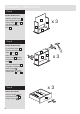
Assembly Instructions Step 9 Prepare the right side A I B Tap a wooden dowel A into the right side 2 . E I R C B O b B 2 Screw 3 metal dowels B into the right side 2 . L Insert a large locking cam nut E into the right side 2 . Finished front edge L 2 1st I screw L Finished front edge Fit a CR runner O b to the right side 2 . O b The 1st screw I uses the 1st hole in from the front of the runner O b . CR The 2nd screw I uses the hole that lines up with the other panel hole.
Assembly Instructions Step 11 B Join the right side and base E CR 2 Push the base 4 onto the right side 2 . Finished front edge Use a screwdriver to tighten the 2 large locking cam nuts E fitted to the base 4 . pla in c Note: Turn the large locking cam nuts E as far as they will go - more than 1/2 a turn. Step 12 4 hip bo ard sur fac e Finished front edge E A Prepare the plinth in la p Tap 2 wooden dowels A into the plinth 9 .
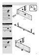
Assembly Instructions Step 14 Fit the left side CR Push the left side 1 onto the assembly. Use a screwdriver to tighten the 3 large locking cam nuts E fitted to the base 4 and plinth 9 . 4 1 9 Step 15 K Prepare the top Screw 6 metal dowels B into the top 3 . B Fit the 2 brackets from the overbalance protector kits K to the shallow mark-holes drilled into the top 3 using 1 of their screws. Note: Only fit 1 of the screws, the other 1 will be fitted later.
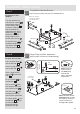
Assembly Instructions Step 16 E Prepare the divider a: Insert 2 large locking cam nuts E into the divider 5 . E a: 5 Finished front edge Note: The 2 holes for the large locking cam nuts may be drilled in either surface of the divider .5 . Fit a CR runner O b to this surface of the divider 5 . 1st I screw b: O b I 5 CR I R C Note: Use the finished front edge to identify which runner to fit. O b Finished front edge The 1st screw I uses the 1st hole in from the front of the runner.
Assembly Instructions Step 17 Fit the divider 5 CR Push the divider 5 onto the top 3 . Finished front edge Use a screwdriver to tighten the 2 large locking cam nuts E fitted to the divider 5 . 3 Note: The 2 large locking cam nuts may be on either surface of the divider. E Step 18 E I Prepare the upright a: Insert 2 large locking cam nuts E into the upright 6 . R C a: O b CR Finished front edge The 1st screw I uses the 1st hole in from the front of the runner.
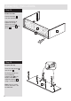
Assembly Instructions Step 19 Fit the upright Push the upright 6 onto the top 3 . 3 CR Use a screwdriver to tighten the 2 large locking cam nuts E fitted to the upright 6 . CR 6 Finished front edge Step 20 Fit the top 2 3 CR Use a screwdriver to tighten the 2 large locking cam nuts E fitted to the side panels . 1 and 2 . 6 CR Secure the upright 6 to the base 4 using screw .C . CR Push the top 3 onto the side panels 1 and .2 .
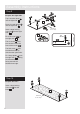
Assembly Instructions Step 21 Squaring up a Chest and fitting the Back Panel www.youtube.com/watch?v=FeaI6541z7o Fit back panel a: Square up the unit by a: making sure that measurement x to x equals y to y. b: Place the back The measurement from top corner X to bottom corner X must be equal to the measurement from top corner Y to bottom corner Y b: 16 down onto the unit, as shown. D Nail D around the outside edges of the back 16 . Note: Nails should be spaced about 150mm apart.
Assembly Instructions Step 22 Secure the unit to a wall a: Before fitting the unit to a wall, use a spirit level to check the top of the unit is level, front-to-back and side-to-side in the 3 positions shown. Use suitable packing pieces (not supplied) to make the unit level. To prevent possible overbalancing this unit must be secured to a suitable wall by fitting of the 2 overbalance protector kits K to a wall. b: Push the unit up against the wall and slide the brackets against the wall.
A Guide to Wall Mounting & Fixings Important: When drilling into walls always check that there are no hidden wires or pipes etc. Important note: If plastic wall plugs are supplied with your product: Make sure that the screws and wall plugs being used are suitable for supporting your unit. Consult a qualifed tradesperson if you are unsure. Hints: - these are only suitable for use in masonry walls. If you are in any doubt about the correct wall plugs for your wall, seek professional advice.
Assembly Instructions Step 23 Fit the shelf Insert 8 shelf studs J at the required height for the large shelf 7 and the small shelf 8 . J x4 Lower the large shelf 7 and small shelf 8 down onto the shelf studs J . 7 J x4 8 Step 24 Prepare the doors Hinge Fixing and Door Adjustment www.youtube.com/watch?v=wIMhUHeLBtg Push fit 2 hinges M into each of the doors 15 . H H H Secure each hinge with 2 screws H .
Assembly Instructions Step 25 Drill the handle holes in the door Important: Please follow these instructions carefully. IMPORTANT You will need to drill the doors to suit the handles supplied You will need to drill 2 doors as shown in this diagram ONLY drill these 2 holes Lay the doors 15 down onto a smooth surface. Important: Check that the holes and hinges are in the same place as the diagrams.
Assembly Instructions Step 26 Hinge Fixing and Door Adjustment www.youtube.com/watch?v=wIMhUHeLBtg Fit doors and handles Note: The easiest way to attach each door 15 is to fit the top hinge first, then align and fit the other hinge. a: Push the hinge a: L M A M B c: d: L L M M b: Keep the hinge M FLAT against the hinge plate L as you slide it across as far as it will go. Tighten screw A. c: The hinge L M M onto the front part of the hinge plate L .
Assembly Instructions Step 27 Adjust the doors if needed a: Before adjusting the doors, use a spirit level to check the base (or top) of the unit is level, front-to-back and side-to-side in the 3 positions shown. Use suitable packing pieces (not supplied) to make the unit level BEFORE making any adjustment to the hinges, as shown. Hinge Fixing and Door Adjustment www.youtube.com/watch?v=wIMhUHeLBtg a: b: A A b: Height adjustment. Loosen screws A on hinge plates and move door up or down as required.
Assembly Instructions Step 28 Fit the drawers Fixing Bottom Mounted Runners https://www.youtube.com/watch?v=Z6lGMy19h7Q Slide the wheels of the runners fitted to the drawers, over the wheels of the runners fitted to the side panels and push the drawers into position.
Assembly Instructions Step 29 Assembly is complete Please remove any blue protective film from panel edges and clear protective film from panel surfaces 21
ALR2752
ALR2752