Napoli - Shoe Storage Assembly Instructions - Please keep for future reference 932/6936 Dimensions Width - 80cm Depth - 33cm Height - 86cm MADE IN BRITAIN Important - Please read these instructions fully before starting assembly If you need help or have damaged or missing parts, call the Customer Helpline: 08456 400800 Issue 1 - 05/05/11
Safety and Care Advice Important - Please read these instructions fully before starting assembly • Warning: This unit weighs approximately 28kgs. Please lift with care. • Make sure you have enough space to layout the parts before starting. • Check you have all the components and tools listed on pages 2 and 3. • Do not stand or put weight on the product, this could cause damage. • Remove all fittings from the plastic bags and separate them into their groups.
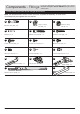
Components - Panels If you have damaged or missing components, call the Customer Helpline: 08456 400800 quoting the reference numbers below Please check you have all the panels listed below 3 Top (D0846A) (797 x 329mm) 1 Left Side (D0844A) (830 x 312mm) 5 Loose Shelf (D0850A) (760 x 308mm) x 3 2 Right Side (D0845A) (830 x 312mm) 4 Base (D0847A) (797 x 329mm) 6 Door (D0849A) (683 x 392mm) x2 7 Drawer Wrap (W429) (1393 x 95mm) 8 Drawer Front (D0848A) (786 x 138mm) 9 Drawer Base (T429) (319 x 740
Components - Fittings If you have damaged or missing components, call the Customer Helpline: 08456 400800 quoting the reference numbers below Please check you have all the fittings listed below Note: The quantities below are the correct amount to complete the assembly. In some cases more fittings may be supplied than are required.
Assembly Instructions Step 1 Prepare the drawer front and wrap If you have damaged or missing components, call the Customer Helpline: 08456 400800 quoting the reference numbers below A a: A a: Screw 2 metal dowels A .A into the holes shown on the back of the drawer front 8 . Note: Tighten the metal dowels up fully against the panel. 8 C b: C b: Insert 2 small locking nuts C into the holes shown on the drawer wrap 7 .
Assembly Instructions Step 3 Attach the handle F F Attach a handle Q to the drawer front 8 using 2 screws F . 8 Q Step 4 Finished front edge Fit runners to left side Place a runner P on the left side 1 . Slide back the top of runner and use the 2nd hole from the front to fit the 1st screw J . b: Slide runner back the other way and use 2nd hole from the back to fit 2nd screw J .
Assembly Instructions Step 5 P J a: a: Place a runner P on the right side 2 . Slide back the top of runner and use the 2nd hole from the front to fit the 1st screw J . 2 J P Finished front edge Finished front edge Fit runners to right side b: Slide runner back the other way and use 2nd hole from the back to fit 2nd screw J . Rebated back edge b: J J P 2 Finished front edge c: Insert 2 large locking nuts B into the right side 2 .
Assembly Instructions Step 6 Prepare the top Note: The top and base panels are very similar but, the holes in the top panel are not drilled all the way through. G A M A M Fix a bracket to the middle of the top 3 , flush to the back edge, using screw G . M A 3 A Finished front edge Screw 4 metal dowels A into the holes shown on the top 3 . Step 7 Join the top and right side Push the top 3 onto the right side 2 . Use a screwdriver to tighten the 2 large locking nuts B fitted to the right side 2 .
Assembly Instructions Step 8 Fit the left side Push the left side 1 onto the top 3 . 3 Use a screwdriver to tighten the 2 large locking nuts B fitted to the left side 1 . Note: Turn the large locking nuts B as far as they will go - more than 1/2 a turn. 1 Finished front edge Step 9 Fit the base Attach the base 4 to the left side 1 and right side 2 using 4 screws .E .
Assembly Instructions Step 10 Fit the plastic nails Tap the plastic nails K into the base 4 as shown. 2 The plastic nails K must go up into the bottom edge of the left side 1 and right side 2 . K 1 4 K K K Step 11 a: Fit the back The measurement from top corner X to bottom corner X must be equal to the measurement from top corner Y to bottom corner Y a: Square up the unit by making sure that measurement x to x equals y to y. b: Place the back b: x D 10 onto the unit.
Assembly Instructions Step 12 Secure unit to a wall M 3 WALL To prevent possible overbalancing we recommend that this unit is secured to a suitable wall by use of the metal bracket M fitted under the top 3 of the unit. Top of unit M Fixings are not supplied as they will need to suit the wall type, and the length of screw will depend on the distance of the back of the unit to the wall. Warning: Take care when drilling the wall that you do not drill into any pipes, wires etc.
Assembly Instructions Step 14 Fit the shelves Lower the 3 shelves 5 down onto the shelf studs L . 5 5 5 Step 15 I Fit the drawers Slide both the runners P forward and locate the sides of the drawer wrap . 7 between them, lining up the holes in the drawer wrap with the 2nd 'threaded' holes in the runners P . Working from the inside of the drawer, insert 2 screws I through the drawer sides and out into the 2nd threaded hole in the runner P . Note: Do not overtighten the screws I .
Assembly Instructions H Step 16 x2 H Prepare the doors O Push fit 2 hinges O into each door 6 . Secure each hinge with 2 screws H . 6 90 H H O O Note: Before securing with the screws, make sure that the hinges are positioned at 90 degrees with the edge of the door. Step 17 Drill 2 handle holes in each door Important: Please follow these instructions carefully. Important: Check that the hinges and holes are in the same place as these diagrams.
Assembly Instructions Step 18 Fit doors and handles a: N N O onto the front part of the hinge plate N . The recess at the bottom of screw B goes into the slot in the hinge plate. b: Keep the hinge N O O Note: The easiest way to attach each door 6 is to fit the top hinge first, then align and fit the other hinges. a: Push the hinge b: A B c: O d: N N O O B O FLAT against the hinge plate N as you slide it across as far as it will go. Tighten screw A.
Assembly Instructions Step 19 Adjust the doors if needed a: a: Before adjusting the doors, use a spirit level to check the base (or top) of the unit is level, front-to-back and side-to-side in the 3 positions shown. Use suitable packing pieces (not supplied) to make the unit level BEFORE making any adjustment to the hinges, as shown. b: A A b: Height adjustment. Loosen screws A on hinge plates and move door up or down as required. Retighten screw A. c: B c: Forward and Back adjustment.
Assembly Instructions Step 20 Assembly is complete If you need help or have damaged or missing parts, call the Customer Helpline: 08456 400800 and quote the reference numbers on the component pages.