*Font used is Helvetica Black Condensed,32pt WITH HP ELECTRONICS Owner’s Manual ©2008 Manufactured by: HELLENBRAND, INC. 404 Moravian Valley Road • Waunakee, Wisconsin 53597 Phone: 608-849-3050 • Fax 608-849-7398 Web: www.hellenbrand.com • Email: info@hellenbrand.
This owner’s manual is designed to assist owners and installers with the operation, maintenance and installation of your new water softener. It is our sincere hope that this manual is clear, concise and helpful to both owner and installer. We have included detailed instructions on general operating conditions, pre-installation and installation instructions, start-up, and timer and meter programming. We have included a troubleshooting guide, service instructions and parts diagrams to assist you.
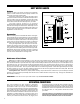
Job Specification Sheet MODEL NO.
Soft Water Basics Hardness Hardness in water is the amount of calcium and magnesium present. A water softener removes the majority of calcium and magnesium to produce softened water. Hardness is measured in units of grains per gallon. When your water is tested the hardness is calculated and expressed as grains per gallon (gpg). This calculation, as well as the number of people in your household will help determine what type and size of water softener will most efficiently soften your water.
Pre-Installation Check List (All electrical & plumbing should be done in accordance to all local codes) Water Pressure: A minimum of 25 pounds of water pressure (psi) is required for regeneration. Maximum 125 psi. Water Quality: On rural water supplies there is often a problem with sand or sediment in the water. (This problem occasionally occurs in public water supplies.
Installation Instructions (All electrical & plumbing should be done in accordance to all local codes) • Do not use vaseline, oils, other hydrocarbon lubricants or spray silicone anywhere. A silicon lubricant may be used on black o-rings but is not necessary. Avoid any type of lubricants, including silicone, on red or clear lip seals. • Do not use pipe dope or other sealants on threads. Only teflon tape may be used on threads.
Programming 12:00pm General Information The H125 control valve is the “brain” of your water softener. It consists of the valve body and powerhead with solid state microprocessor. The display panel (see Figure 7) consists of the LCD display and five push buttons which are used in displaying and programming the water softener settings. Initial Start Up The initial start up will probably be done by the technician installing the softener system.
SET TIME OF DAY = Up Arrow Step 1 SET Step 1 - Press SET CLOCK. Step 2 - Current Time (hour): Set the hour of the day using or buttons. AM/PM toggles after 12. Press NEXT to go to step 3. TIME HOUR SET 6:35 PM Step 2 Step 3 - Current Time (minutes): Set the minutes of day using or buttons. Press NEXT to exit Set Clock. Press REGEN to return to previous step. Power Loss - Lithium battery on circuit board provides up to 2 years of time clock backup during power outages.
Manual Regeneration Sometimes there is a need to regenerate the system, sooner than when the system calls for it, usually referred to as manual regeneration. There may be a period of heavy water usage because of guests or a heavy laundry day. "REGEN TODAY" CAPACITY REMAINING 320 To initiate a manual regeneration at the preset delayed regeneration time, press and release “REGEN”.
SOFTENING TIME SET 120:00 Step 4S STEP 4 S – Select the time for the second cycle (which in this example is SOFTENING) using or button. Press NEXT to go to Step 5S. Press REGEN to return to the previous step. Step 5S STEP 5 S – Select the time for the third cycle (which in this example is BACKWASH) using the or button. Press NEXT to go to Step 6S. Press REGEN to return to the previous step.
DELAY + IMMEDIATE SET REGEN STEP 12 S – Set Regeneration Time Options using the or button.
RELAY 1 SET POINT SET REGEN If REGEN gallons chosen to activate relay. Relay activates after set number of gallons have been used in service and if any water is used during regeneration and then deactivates after set period of time or after flow stops, whichever comes first. Press NEXT to select number of gallons per relay activation. GAL RELAY 1 SETPOINT SET 1 Step 18S GAL STEP 18 S – Use up and down arrows to set number of gallons per relay activation. Range 1-100 gallons.
DIAGNOSTICS = Up Arrow = Down Arrow Reset Diagnostic Values: Hold UP/DOWN buttons for 3 seconds. DAYS SINCE REGEN 2 NEXT/DOWN buttons for 3 seconds, then hold Step 1D STEP 1D – Press or simultaneously for three seconds. If screen in step 2D does not appear in 5 seconds the lock on the valve is activated. Step 2D STEP 2D – Days, since last regeneration: This display shows the days since the last regeneration occurred. Press the NEXT button to go to Step 3D. Press REGEN to exit Diagnostics.
VALVE HISTORY (Can not be reset) STEP 1VH – Press and simultaneously for three seconds and release, then press and simultaneously and release. If screen in step 2VH does not appear in 5 seconds the lock on the valve is activated. Step 2VH STEP 2VH – Days, total since start-up: This display shows the total days since startup. Press the NEXT button to go to Step 3VH. Press REGEN to return to previous step.
CYCLE SEQUENCE Anytime cycle sequence is modified, softener set-up will revert to manufacturer setting and must be reprogrammed as desired. Cycle Sequence instructions allows the operator to set the order of the cycle. The Softener System Setup allows the operator to set how long the cycles will last. The operator may choose up to 9 cycles in any order. Cycle Options REGENERANT DRAW-DN SOFTENING BACKWASH RINSE FILL END END must be used as the last cycle option.
Only displays if reclamation of brine is enabled in Step 3CS. Selection requires that a connection to a MAV is made to the two-pin connector labeled DRIVE on PC Board. RECLAMATION MODE SET ENABLED Press NEXT to go to Step 4CS. Press REGEN to return to previous step.
AUXILIARY INPUT OFF SET Step 8CS REG BACKWASH SET CYCLE1 Step 9CS STEP 8CS – If Twin Alternating capability is selected, auxilliary input option is not available. This display will be available to select the use of an outside signal to control the initiation of a regeneration. Selection only matters if a connection is made to the two pin connector labeled DP SWITCH located on the printed circuit board.
Water Softener Disinfection The materials of construction of your water softener will not support bacterial growth nor will these materials contaminate a water supply. However, the normal conditions existing during shipping, storage, and installation indicate the advisability of disinfecting a softener after installation, before the softener is used to treat potable water. In addition, during normal use a softener may become fouled with organic matter or in some cases, with bacteria from the water supply.
Trouble Shooting 1. PROBLEM CAUSE ERROR followed by code number Error Code 101 - Unable to recognize start of regeneration A1. Not reading piston position, valve has been recently serviced A2. Incorrect Assembly A1. Resynchronize software with piston position, Press NEXT & REGEN for 3 seconds or until display is blank A2. Disassemble drive bracket, verify wires are in guides & reassemble. Verify motor is plugged into PC board Error Code 102 - Unexpected stall B.
Trouble Shooting PROBLEM CAUSE 8. Loss of resin. A. Backwash controller missing. B. Faulty distributor tube assembly. C. Air in water supply system. A. Install backwash controller. B. Check distributor tube assembly for cracks or holes. C. 1. Check for leaks in brine lines, fittings, or air check. Repair or replace. 2. Install upper distributor. 3. Ensure that water supply system has an air eliminator. 9. Softener delivers salt water. A. Low water pressure. B. Excessive water in brine tank. C.
relay troubleshooting PROBLEM CAUSE CORRECTION 20. Relay does not energize A. Relay driver programmed on "Time" B. Relay driver programmed on "Gallons" 21 A. Programmed incorrectly B. Faulty wire connections between PC board and relay C. Defective PC Board D. Defective relay, See figure below C. Replace PC Board D. Replace Relay A. B. C. D. E. A. B. C. D. E.
H125 conditioner & salt keeper assemblies Item 1 2 3&4 Description Control Center-Metered Top Diffuser Mineral Tank Assembly Qty 1 1 5 H125-32-10 10 x 44 H125-48 10 x 54 H125-64 13 x 54 H125-96 14 x 65 H125-128 16 x 65 H125-160 18 x 65 Ion Exchange Resin 1 1 1 1 1 1 * * * 1 1 1 1 1 1 1 1 1 1 1 1 1 1 1 1 1 6 7 7-15 a b c d e f g h i j 8a b c d 9 Underbedding 3/8” x 6' Brine Line 18X40 w/474 SBV & 5" Grid 18X40 w/474 SBV & 8" Grid 18X40 w/474 SBV & 11" Grid 24x41w/474 SBV & 6" Grid 24x50 w/474 SBV & 6"
FRONT COVER AND DRIVE ASSEMBLY DRAWING NO. ORDER NO.
DRIVE CAP ASSEMBLY, DOWN FLOW PISTON, REGENERANT PISTON AND SPACER STACK ASSEMBLY DRAWING NO. 1 2 3 4 5 6 7 8 ORDER NO. DESCRIPTION 151-V3430 15-V3004 15-V3343 151-V3407 15-V3174 15-V3135 15-V3180 151-V3358 H125 Spacer Stack Assembly Drive Cap Assembly H125 Drive Back Plate H125 Piston Downflow Assy Regenerant Piston O-ring 228 O-ring 337 O-ring 219 (Dist. Tube Opening 1.32") QUANTITY 1 1 1 1 1 1 1 1 3 Note: The regenerant piston is not used in backwash only application.
REFILL FLOW CONTROL ASSEMBLY AND REFILL PORT PLUG 3/8” – for systems up to 150,000 grains (*Assembly includes #8.
drain line - 3/4” ITEM NO. 1 2 3 4-6 5 6 7 ORDER NO. 15-H4615 15-PKP10TS8 15-V3192 15-V3158-01 15-V3163 15-V3159-01 15-V3162-007 15-V3162-010 15-V3162-013 15-V3162-017 15-V3162-022 15-V3162-027 15-V3162-032 15-V3162-042 15-V3162-053 15-V3162-065 15-V3162-075 DESCRIPTION Elbow Locking Clip Polytube Insert, 5/8” Nut 3/4” Drain Elbow Drain Elbow 3/4” Male Assy O-ring 019 DLFC Retainer Assy. DLFC 0.7 gpm for 3/4” DLFC 1.0 gpm for 3/4” DLFC 1.3 gpm for 3/4” DLFC 1.7 gpm for 3/4” DLFC 2.2 gpm for 3/4” DLFC 2.
water meter and meter plug ITEM NO. 1 2-4 3 4 5 ORDER NO. 15-V3151 15-V3003* 15-V3118-01 15-V3105 15-V3003-01 DESCRIPTION Nut 1” QC Meter Assy. Turbine Assy. O-ring 215 Meter Plug Assy.** QTY. 1 1 1 1 1 *Order number 15-V3003 includes 15-V3118-01 and 15-V3103, which are item numbers 3 & 4. **Only used if metering is not to be done (time clock units) The nuts and caps are designed to be unscrewed or tightened by hand or with the special plastic wrench.
Installation fitting assemblies ITEM NO. 1 2 3 4 1-4 DESCRIPTION ORDER NO. 15-V3151 15-V3150 15-V3105 15-V3164 15-V3007-04 Nut 1” Quick Connect Split Ring O-Ring 215 Fitting 1” Plastic Male NPT Fitting 1” Male NPT Asy. (Set of 2) ITEM NO. QTY. 1 2 3 4 1-4 2 2 2 2 1 Figure 22 ITEM NO. 1 2 3 4 1-4 DESCRIPTION ORDER NO.
Order No: 15-V3007-13 Description: IC 2.0 Fitting 1” Brass SharkBite Assembly Order No: 15-V3007-12 Description: IC 2.0 Fitting 3/4” Brass SharkBite Assembly ITEM NO. 1 2 3 4 ORDER NO. 15-V3151 15-V3150 15-V3105 15-V3628 DESCRIPTION Nut 1” Quick Connect Split Ring O-Ring 215 Fitting 3/4” Brass SharkBite QTY. ITEM NO. 2 2 2 2 1 2 3 4 ORDER NO. 15-V3151 15-V3150 15-V3105 15-V3629 DESCRIPTION Nut 1” Quick Connect Split Ring O-Ring 215 Fitting 1” Brass SharkBite QTY.
FLOW DIAGRAMS – SERVICE AND BACKWASH 30
FLOW DIAGRAMS – DOWNFLOW 31
FLOW DIAGRAMS – RINSE AND FILL 32
H125 H125Specifications SPECIFICATIONS Model # Factory Regeneration Settings Backwash Minutes Gallons Brine/Rinse Minutes Gallons Backwash Minutes Gallons Fast Rinse Minutes Gallons Fill Minutes Gallons H125 32-10 H125 48 H125 64 H125 96 H125 128 H125 160 H125 192 8 18 60 19.2 8 18 4 9 6:32 3.2 66 8 18 60 22.2 8 18 4 9 9:53 4.7 71 8 34 68 43.5 8 34 4 17 13:14 6.5 134 8 34 68 47.7 8 34 4 17 19:56 9.8 142 8 42 68 71.1 8 42 4 21 26:38 13.2 190 8 60 68 89.1 8 60 4 30 33:20 16.
Programming options Reserve Gallons Regeneration Type Days Override AUTO DELAY oFF AUTO DELAY 1 to 28 20 to 250,000 DELAY oFF oFF DELAY 1 to 28 Reserve capacity not automatically estimated. Regeneration occurs at the next Regen Set Time when the specified number of days between regenerations is reached. 20 to 250,000 DELAY 1 to 28 Reserve capacity not automatically estimated.
SERVICE INSTRUCTIONS Drive Assembly Remove the valve cover to access the drive assembly. Disconnect the power source plug (black wire) from the PC board prior to disconnecting the motor or water meter plugs from the PC board. The power source plug connects to the four-pin jack. The motor plug connects to the two-pin jack on the left-hand side of the PC board. The water meter plug (gray wire) connects to the three-pin jack on the far right-hand side of the PC board.
The regenerant piston (the small diameter one behind the main piston) is removed from the main piston by pressing sideways and unsnapping it from its latch. Chemically clean this in dilute sodium bisulfite or vinegar, or replace the regenerant piston if needed. To remove the main downflow or upflow piston fully extend the piston rod and then unsnap the main piston, from its latch by pressing on the side with the number. Chemically clean this in dilute sodium bisulfite or vinegar, or replace the main piston.
Refill Flow Control Assembly or Refill Port Plug To clean or replace the refill flow control, pull out the elbow-locking clip and then pull straight up on the elbow. Replace the elbow locking clip in the slot so that it is not misplaced. Twist to remove the white flow control retainer. The flow control can be removed by prying upward through the side slots of the retainer with a small flat blade screwdriver.
H125 Series Water Softeners limited warranty Hellenbrand, Inc., warrants to the original consumer purchaser that the H125 Series and the parts listed below will be free from defects in material and/or workmanship from the date of the original installation for the following time periods: For a Period of FIVE YEARS: The control valve including electrical parts, internal parts, and valve body. For a Period of TEN YEARS: Mineral tanks, 6” Diameter - 13” Diameter.