COMPACT PRINTER SERIES CP-2140 CP-2140E USER’S MANUAL 1 Website: http://www.argox.
Table of Contents Introduction ....................................................................... 4 Proprietary Statement ................................................... 4 Product Improvements ................................................. 4 FCC Compliance Statement ......................................... 4 Liability Disclaimer ........................................................ 4 Safety ........................................................................... 5 Getting Started ........
Miscellaneous ............................................................. 36 Recovery..................................................................... 37 Communications ............................................................. 38 Interfaces and Requirements ...................................... 38 USB Interface Requirements .................................. 38 Serial (RS-232) Interface Requirements ................. 39 Parallel Interface Requirements..............................
Introduction Proprietary Statement This manual contains proprietary information of Argox Information Co., Ltd. It is intended solely for the information and use of parties operating and maintaining the equipment described herein. Such proprietary information may not be used, reproduced, or disclosed to any other parties for any other purpose without the expressed written permission of Argox Information Co., Ltd. Product Improvements Continuous improvement of products is a policy of Argox Information Co.
without limitation, damages for loss of business profits, business interruption, loss of business information, or other pecuniary loss) arising out of the use of or the results of use of or inability to use such product, even if Argox Information Co., Ltd. has been advised of the possibility of such damages. CAUTION: Any changes or modifications not expressly approved by the party responsible for compliance could void the user's authority to operate the equipment.
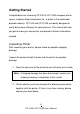
Getting Started Congratulations on choosing CP-2140 & CP-2140E compact printer series, made by Argox Information Co., a leader in the world-wide barcode industry. CP-2140 and CP-2140E are ideally designed to easily bring more efficiency for your business. This manual will help you get to know your new printer and provide sufficient information needed.
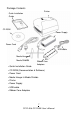
Package Contents Printer Quick Installation Guide CD ROM Power Supply Power Cord USB cable Media Hanger & Media Shields Ribbon Core Adaptors Quick Installation Guide CD ROM (Documentation & Software) Power Cord Media Hanger & Media Shields Printer Power Supply USB cable Ribbon Core Adaptors 7 CP-2140 & CP-2140E User‟s Manual
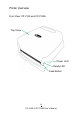
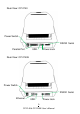
Printer Overview Front View: CP-2140 and CP-2140E Top Cover Power LED Ready LED Feed Button 8 CP-2140 & CP-2140E User‟s Manual
Rear View: CP-2140 Power Switch RS232 Serial Parallel Port USB Power Jack Rear View: CP-2140E Power Switch RS232 Serial Ethernet Power Jack USB 9 CP-2140 & CP-2140E User‟s Manual
Interior View I Media Shields Ribbon Pick-up Holder Media Hanger Module Release Latch PUSH 10 CP-2140 & CP-2140E User‟s Manual
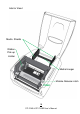
Interior View II Top Cover Ribbon Supply Holder Media Shaft Print Head Transmissive Sensor Media Guides Platen Roller Power LED Reflective sensor Ready LED Front Cover Feed Button Head-Open Sensor 11 CP-2140 & CP-2140E User‟s Manual
Attaching Power 1. Make sure the printer‟s power switch is in the off position (down). 2. Insert the AC power cord into the power supply. 3. Insert the power supply‟s power connector into the printer‟s power jack. 4. Plug the other end of the power cord into an appropriate grounded AC electrical outlet. Warning: Do not operate the printer and power supply in an area where they might get wet.
CP-2140E Power Jack Power Connector Power Supply Power Cord 13 CP-2140 & CP-2140E User‟s Manual
Loading Media Preparing Media The inside wound or outside wound media rolls can be loaded into the printer in the same way. In case media roll may become dirty or dusty during shipment, handling, or storage, firstly remove the outside length of media, which helps to avoid dragging adhesive or dirty media between the print head and platen roller. When loading media, it must be placed onto the media hangers. Placing Media Roll 1. Open Top Cover of the printer.
2. Put the Media Hanger through media supply roll, and then centrally align with the two Media Shields to closely lean against the media supply roll. Media Hanger Media Shield 3. Locate the media supply roll into the Media Compartment of printer.
4. Push the Release Latch to open the printer module. PUSH Module Release Latch 5. Pull a short length of media till it reaches the Platen Roll of printer.
6. Press the lock of Media Guide at the right to adjust media guides‟ positions. Make sure media stays under the Media Shaft and centrally under both of the Media Guides. Media Shaft Media Guides 7. Close the printer module and then press firmly at the both sides to properly latch until you hear a click.
8. Press the FEED button to feed labels out of the printer. 9.
Setting Media Type To index labels with multiple columns, please select media types to Multi-Column Labels in the label editing software Bartender UL.
Loading Ribbon The following steps only apply to thermal transfer printing mode only. Direct thermal does not need ribbon to be installed. Note: - Media and ribbon types should be matched to provide with optimal print results. - Always use ribbon that is wider than the media to protect the print head from wear. - For direct thermal printing, do not load ribbon in the printer.
Placing Ribbon Rolls 1. Open Top Cover of the printer. Top Cover 2. Push the Release Latch to open the printer module.
3. Lift up the printer module to check the Ribbon Supply Holder.
4. Install one ribbon roll and rotate it until the notches align and lock into the left side of Ribbon Supply hub, and then into the right. Ribbon Supply Holder Note: The Ribbon Supply Holder accepts the coated side of ribbon to be wound ink-side IN or wound ink-side OUT.
5. Install the other ribbon roll and rotate it until the notches align and lock into the left side of Ribbon Pick-up hub, and then the right. Ribbon Pick-up Holder Note: The Ribbon Pick-up Holder accepts the coated side of ribbon to be wound ink-side OUT only.
6. Close the printer module and then press firmly at the both sides to properly latch it until you hear a click. 7. Rotate Thumb Wheel of Ribbon Pick-up Holder to remove slack and ribbon wrinkle, and to align the ribbon on the spindles.
Printer Operations Printing Media Calibration & Configuration Before connecting the printer to your computer, to make sure that the printer works properly, conduct media calibration and print a self-test/ configuration label. Steps to Start Media Calibration & Configuration 1. Make sure the media is properly loaded and the top cover of the printer is closed. 2. Turn off the printer power. 3. Press and hold the FEED button while turning on the power, until printer motor is activated. 4.
Sample of Printer Configuration Label Firmware version & date code Memory capacity Codepage Print method Media sensor type Real Time Clock (RTC) setup (available only with RTC Card) Internal fonts Printed label length Serial port settings Print speed and darkness Media type setting Print width setting Label length setting Backfeed setting Cutter setting Calibration mode type 27 CP-2140 & CP-2140E User‟s Manual
Ethernet information for CP-2140E only Main board DIP switch settings Print head test pattern 28 CP-2140 & CP-2140E User‟s Manual
Resetting Printer to Factory Defaults Follow the steps below to reset printer to default settings: 1. Turn on the printer and wait for 5 or more seconds. 2. Press the "FEED" button for 10 seconds, and the "Ready" indicator and "Power" indicator will go off in order. 3. Once "Power" indicator becomes lit again, release the FEED button. 4. "Ready" indicator will then become lit, too. At this moment, the printer has resumed its factory default settings.
Printer Controls and Indicators Power Switch Power LED Ready LED Feed Button The following table explains printer controls and indicators‟ functions to help understanding LED indications and printer status: 30 CP-2140 & CP-2140E User‟s Manual
Control / Indicator Power Switch Function On: turns on normal operation (at “I” position) Off: turns off power ( at “O” position) Note: Turn power off before connecting or disconnecting cables Power LED It will start blinking while “Media Out”, “Media Gap Not Found” or “Ribbon Out” has been detected. Once printer cutter mode has been enabled, when Cutter is jammed with paper or Cutter is not installed, POWER indicator will blink.
Note: When the print head is over-heated, printer‟s thermal protection function will be activated and make READY LED blink to indicate printer is in PAUSE status to wait till print head has been cooled down. The printing tasks sent previously will be resumed automatically later. Feed Button Press to advance the label media to the first printing position. Press during printing to make printer "pause".
Troubleshooting by LED Indicators Diagnosis Normally, when the printer is in not working properly, the "Power" LED blinks continuously, and printing and communication between the host and printer stops. Refer to LED indications listed below to understand possible solutions to resolve the problems printer run into.
LED Indicators: Power and Ready LEDs blink alternately Power LED Ready LED ON OFF OFF ON Possible Problems Solutions Remarks Install a new ribbon roll Set “Direct Thermal” printing by driver or commands if no ribbon is required. Ribbon out LED Indicators: Only the Power LED blinks Power LED Ready LED ON ON OFF ON Possible Problems Solutions Remarks Serial IO error Check serial baud rate at For serial interface only both of your system and the printer.
LED Indicators: Only the Ready LED blinks Power LED ON ON Ready LED ON OFF Possible Problems Print head needs to cool down Printer head module unlatched Printer is in PAUSE status Printer is receiving data Solutions Printing will stop until the print head cools to normal printing temperature. Once it completes, the printer will automatically resume the printing tasks sent previously. Close the printer module and then press firmly at both the left and the right of printer module to properly latch.
Miscellaneous If the host shows "Printer Time out": 1. Check if the communication cable (serial) is connected securely to your serial port on the PC and to the connector on the printer at the other end. 2. Check if the printer power is turned on. If the data has been sent, but there is no output from the printer. Check the active printer driver, and see if Seagull driver for your Windows system and the label printer has been selected.
Poor printout quality: The ribbon may not be qualified. The media may not be qualified. Adjust the Darkness (heat temperature). Slow down the print speed. Refer to the next chapter and clean the related spare parts. Recovery After correcting problems, simply press the panel button or restart the printer to continue your print jobs. Make sure the LEDs are not blinking and remember to resend your files.
Communications Interfaces and Requirements Argox CP printer series come with a nine-pin Electronics Industries Association (EIA) RS-232 serial data interface, a USB interface, Parallel, and Ethernet. A variety of interface options are suitable for versatile applications: CP-2140: Parallel, USB, and Serial interfaces CP-2140E: Ethernet, USB, and Serial interfaces Note: 1.
Serial (RS-232) Interface Requirements The required cable must have a nine-pin "D" type male connector on one end, which is plugged into the mating serial port located on the back of the printer. The other end of the signal interface cable connects to a serial port on the host computer. Note: For technical and pin-out information, please refer to the Technical Reference, Interface Specifications in this manual.
3. Do not tie the data cables to power wire conduits. Ethernet 10/100 Internal Printer Server Option This connector is for Ethernet application; it is convenient to use several printers by Ethernet connector at the same time. Note: When using Ethernet model printer, please wait till the Ready Indicator to stop blinking, before starting printer operations. Ethernet Module Status Indicators LED Status Both Off Blinking Green Amber Description No Ethernet link detected.
Communicating with the Printer The bundled printer driver can be applied to all applications under Windows 2000/ 2003/ XP/ Vista/ Windows 7, supporting 32-bit/ 64-bit operation systems. With this driver you can operate any popular Windows software applications including Argox Bartender UL label editing software or MS Word, etc., to print to this printer. The following installation steps are based on CP-2140 as an example.
1. Turn off the printer. Plug the power cable into the power socket on the wall, and then connect the other end of the cable to printer's power socket. Connect the USB cable to the USB port on the printer and on the PC. 2. Turn on the printer. If the printer supports Plug-and-Play, and you have successfully connected it using a USB cable, then the Windows Add Hardware Wizard will automatically detect the printer and display a dialog that allows you to install a driver.
4. Under CP-2140/ CP-2140E product selection prompt, choose Seagull Driver version and then start installation: Instead of the flash prompt above, another way to install Seagull driver is to run the DriverWizard utility from the Installation Directory where the Seagull driver files are located.
5. On the Seagull Driver Wizard prompt, select the first radio button to “Install a driver for a Plug and Play printer”: Then click “Next.
6. Enter Printer name (i.e. Argox CP-2140 PPLB) and select "do not share this printer”, and click "Next" Argox CP-2140 PPLB Argox CP-2140 PPLB 7. Check all the data on the showing screen, if it is correct, click "Finish".
8. After the related files have been copied to your system, click "Finish". Installing printer „Argox CP-2140 PPLB‟… 9. After driver installation is complete, click "Close". The driver should now be installed.
Installing a Printer Driver (for other interfaces except USB) 1. Turn off the printer. Plug the power cable into the power socket on the wall, and then connect the other end of the cable to printer's power socket. Connect the Parallel cable, Serial cable, or Ethernet cable to the proper port on the printer and on your computer. 2. Prepare the documentation and software CD-Rom from printer package and then install to CD-Rom drive of your computer. The CD-Rom will bring out the following prompt.
3. Under CP-2140/ CP-2140E product selection prompt, choose Seagull Driver version and then start installation: Instead of the flash prompt above, another way to install Seagull driver is to run the DriverWizard utility from the Installation Directory where the Seagull driver files are located.
4. On the prompt, Windows Printer Driver, select “I accept…” and click "Next". 5. Assign the directory to keep Seagull driver, (for example: C:\Seagull) and click "Next".
6. Click "Finish". 7.
8. Select model & emulation - the following examples are based on model CP-2140 PPLB: Argox CP-2140 PPLB Argox CP-2140 PPLB 9. Select the port of the printer and click "Next".
10. Enter Printer name (i.e. Argox CP-2140 PPLB) and select "do not share this printer”, and click "Next". Argox CP-2140 PPLB Argox CP-2140 PPLB 11. Check all the data on the showing screen, if it is correct, click "Finish".
12. After the related files have been copied to your system, click "Finish". Installing printer „Argox CP-2140 PPLB‟… 13. After driver installation is complete, click "Close". The driver should now be installed.
Caring for Your Printer Print Head Maintenance Guide To keep the Print Head remain in the best conditions and efficiency and to extend duration for use, regular cleaning action is needed: Note: Always switch off printer power before cleaning. Cleaning Interval It‟s strongly recommended to regularly clean print heads at least when changing every one label roll (in direct thermal printing mode).
Cleaning Direction When cleaning the print head, always wipe in One-Way Direction - from Left to Right only, or, from Right to Left only, to clean “Heating Line” of print head gently without excessive stress. Do not wipe back and forth, to avoid dust or dirt on cleaning cotton would be attached onto print head again. Special Caution: Warranty of print heads will be void if print head serial number is removed, altered, defected, or made illegible, under every circumstance.
Product Specification General Specification Specifications Printing Method Printing Resolution Printing Speed Printing Length Printing Width Memory CPU Type Sensors Operation Interface Communication Interface Fonts 1D Barcodes CP-2140 CP-2140E Direct Thermal / Thermal Transfer 203 dpi(8 dots/mm) 2~4ips (50~102mm/s) Max 100”(2540mm) / Min 0.2” (5mm) Max 4.
2D Barcodes Graphics Emulation Software Label editing Software - Utility Media Type Media Ribbon Dimensions Weight Power Source Operation Environment Optional Items Agency Listing readable check digit), EAN-8 (standard/2 digit add-on/5 digit add-on), EAN-13 (standard/2 digit add-on/5 digit add-on), UPC-A (standard/2 digit add-on/5digit add-on), UPC-E (standard/2 digit add-on/5 digit add-on), Postnet, Codabar, Code 128 subset A/B/C, Code 128 UCC (Shipping Container Code), Code 128 Auto, German, Postcode,
Fonts, Barcodes, and Graphics Specification The specifications of fonts, bar codes and graphics depends on the printer emulation. The emulations PPLA and PPLB are printer programming languages, through which the host can communicate with your printer. Printer Programming Language PPLA Programming Language PPLA 9 fonts with different point size Internal fonts 6 fonts with ASD smooth font. Symbol sets (Code pages) Soft fonts Courier font with different symbol sets.
Printer Programming Language PPLB Programming PPLB Language Internal fonts 5 fonts with different point size Symbol sets (Code pages) Soft fonts 8 bits code page : 437, 850, 852, 860, 863, 865, 857, 861, 862, 855, 866, 737,851,869, 1252, 1250, 1251, 1253, 1254, 1255 7 bits code page: USA, BRITISH, GERMAN, FRENCH, DANISH, ITALIAN, SPANISH, SWEDISH and SWISS.
USB Interface This is port complies with USB 2.0 Full Speed. Connector Terminal Pin Assignment Pin 1 2 3 4 Signal Description VBUS 5V D- Differential data signaling pair - D+ Differential data signaling pair + GND Ground 2 1 3 4 USB series “B” Receptacle Interface Serial Interface The RS232 connector on the printer side is a female, DB-9. Pin 1 2 3 4 5 6 7 8 9 Direction In Out Out In Out Definition Shorted to Pin 6 RxData TxData N.C.
Note : Pin 9 are reserved for KDU (keyboard device unit), therefore do not connect these pins if you are using a general host like a PC. Parallel (Centronics) Interface The parallel port is a standard 36-pin Centronics, which complies with IEEE 1284 standard (compatibility mode). Pin assignments are as follows: Pin 1 2~9 10 11 12 13 14 15 Direction In In Out Out Out Out In - Definition Pin n/STROBE 16 Data 1~8 17 nACK 18 BUSY 19~30 PE 31 5V 32 NC 33~35 NC.
Connection with Host Host 25S Printer 9P (PC or compatible) Host 9S Printer 9P (PC or compatible) DTR 20 DSR 6 TX 2 …… 1 DSR …… 6 DTR …… 2 RX DTR 4 DSR 6 TX 3 …… 1 DSR …… 6 DTR …… 2 RX RX 3 CTS 5 RTS 4 GND 7 …… …… …… …… RX 2 CTS 8 RTS 7 GND 5 …… 3 TX …… 7 RTS …… 8 CTS …… 5 GND 3 TX 7 RTS 8 CTR 5 GND Alternatively you can just connect the 3 wires in the following way.
The simplest way to connect to other hosts (not PC compatible) or terminals is: Printer Terminal/Hos t Pin 2- RxData ……… TxData Pin 3- TxData ……… RxData Pin 5- Ground ……… Ground In general, as long as the data quantity is not too large and you use Xon/Xoff as flow control, it will be problem free. Baud rate: 2400, 4800, 9600(default), 19200, 38400, 57600, 115200 bauds.(programmable by command) Data format: always 8 data bits, 1 start bit and 1 stop bit.
Ethernet Interface The following port complies with Ethernet communication.