Proprietary Statement This manual contains proprietary information of Argox Information Co., Ltd. It is intended solely for the information and use of parties operating and maintaining the equipment described herein. Such proprietary information may not be used, reproduced, or disclosed to any other parties for any other purpose without the expressed written permission of Argox Information Co., Ltd.
A Letter to Our Customers Dear Customers, Congratulation on selecting an Argox OS series printer! We believe soon you will find that you have made a cleverest choice! This booklet is a small gift from us. It is intended for helping you to know your printer better, then further to optimize it. Basically, this booklet contains two parts: operation guidance and related valuable information.
For Win XP....................................................................... 52 For Windows Vista............................................................ 56 Troubleshooting ...................................................................... 59 LED Diagnosis ..................................................................... 59 Miscellaneous ....................................................................... 62 Recovery .......................................................................
Connecting the Power Supply Connect the power supply as below. WARNING: Do not operate the printer and power supply in an area where they can get wet. Make sure the power switch is in the "O" position, and be careful not to touch the 36-pin parallel connector. 1. Insert the barrel connector of the Power Supply into the power jack on the back of the printer. Note the location of the power jack for different models in the diagrams below. 2. Insert the separate power cord into the power supply. 3.
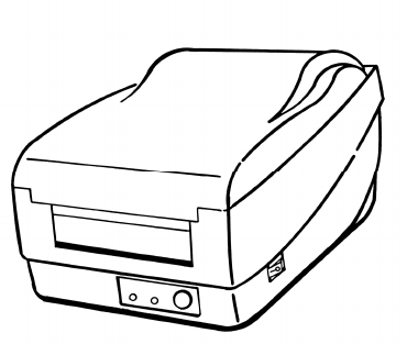
Getting to Know Your Printer There are five models in the OS Series. The OS-214, OS-214Zip and OS-314 share the same parts and features, as do the OS-203 and OS-204. Parts and features of the OS series are illustrated below.
Parts and Features (OS-203, OS-204) Ribbon Pick-up Holder Media Hanger Top Cover H Cover Power Switch Release Levers Power Indicator Feed Button Ready indicator Ribbon Supply Holder Thermal Print head OS-203 / OS-204 Models Platen Roller Power Switch OS-214 / OS-214Zip / OS-314 Models 6 7
Peel-Off Option Cutter Option Media Hanger Release Levers Platen Roller White Plastic Roller Cutter OS-203 / OS-204 Models Thermal Print head OS-203 / OS-204 Models 8 9
Controls and Indicators The printer’s controls and indicators are shown in the diagram below. The following table explains control and indicator functions.
Loading Ribbon and Media Media Compartment This section describes how to load ribbon and media into the OS Series printers. Loading a Ribbon (OS-214, OS-214Zip, OS-314) Print Head Module Release Lever Release Lever Note: This section does not apply to direct thermal printing. 1. Lift the top cover to expose the media compartment. 2. Unlatch the print head module by pushing the two white release levers on the sides toward the rear. 3. Turn over the print head module to expose the ribbon supply holder.
4. Unwrap the ribbon roll pack and separate the ribbon roll and the bare core. 5. Attach the edge of the ribbon on the bare core and wind it a little bit onto the core. 6. Insert the ribbon roll into the supply holder. (First snap in the left side and then the right side.) 7. Put the print head module down and insert the bare core into the pick-up holder. (First snap in the left side, and then the right side.) Ribbon Pick-up Holder Ribbon Supply Holder Bare Core Ribbon Roll Bare Core 14 8.
Loading Media The OS Series printers offer three different loading modes: standard, peel-off, or cutting. Wheel Standard mode allows you to collect each label freely. Peel-off mode peels backing material away from the label as it prints. After a label is removed, the next label prints. Cutting mode automatically cuts the label after it prints. Standard Mode 1. Lift the top cover to expose the media compartment.
2. Remove the media hanger. Media Compartment 4. Click the media hanger back into the media compartment. 5. Align the media roll to the left end. 6. Move the shield from right to left until it leans against the media. Media Hanger Media Compartment 3. Load the media roll onto the hanger from left to right.
7. Unlatch the print head module. 8. Hold the print head module upright with one hand to allow the media to pass under it. Lead the media through the media guides with the other hand. 9. Lead the media over the platen roller. 10. Put the print head module down and press down firmly until you hear a snap. 11. Close the top cover and turn on the printer or press the "FEED" button if the printer is already on.
Peel Off Mode Note: For Peel-off mode you must first install the dispenser kit. Please refer to Appendix I. 10. Trim the front edge of the label backing paper with scissors or a knife. 11. Lead the backing paper into the slot between the dispenser bar and H cover, then ensure it is inserted between the white plastic roller and platen roller. Follow Steps 1 to 8 listed in Standard Mode above. 9. Remove enough labels to expose approximately a 6" length of backing paper.
come out from the slot under the H cover. 13. In OS-203 Peel-off mode, if a misaligned loading occurs keep pressing the "FEED" button to back-feed and reload the label stock. 14. To remove any slack, rewind the media onto the roll. Press down the print head module firmly. "FEED" button if the printer is already on. Note: The "FEED" button does not make the printer peel. Peeling occurs only when the software is properly set. Label H Cover Feed Button Slot 15.
11. Close the top cover and turn on the printer or press the "FEED" button if the printer is already on. Cutting Mode Note: For Cutting mode you must first install the cutter. Please refer to Appendix II. Note: The "FEED" button does not make the printer cut. Cutting occurs only when the software is properly set. Follow Steps 1 to 8 listed in Standard Mode above. 9. Thread the media over the platen roller, then route the media through the slot of the cutter module. 10.
Calibration and Configuration This section discusses calibration, printing configuration and resetting the printer to factory defaults. Performing Calibration and Configuration 1. Turn off the printer power. 2. Press and hold the feed button while turning on the power, then the printer will execute calibration to let machine automatically stock length of the label. (Please continuous to press the feed button when machine executes calibration.) 3.
Computer Connections Power Jack Note: You must insert the power supply’s barrel connector into the power jack on the back of the printer before connecting communication cables. This printer comes with both a nine-pin Electronics Industries Association (EIA) RS-232 serial data interface (for OS-203, it is six-pin) and a standard Centronics parallel interface. In either case, you must supply the required interface cable for your application.
Parallel Interface Requirements Communicating with the Printer The required cable (IEEE 1284-compliant is recommended) must have a standard 36-pin parallel connector on one end, which is plugged into the parallel port located on the back of the printer. The other end of the parallel interface cable connects to the printer connector at the host computer. For pin-out information, refer to the Reference Technical Information, Interface Specification.
3. Select a driver for your printer and click "Next". For 203 dpi modes with 4 inches print width, you should select Label Dr. 200 (4 inch model). 4. Select the port of the printer and click "Next". 5. After the related files have been copied to your system, click “Next”. 6. After the installation is complete, click “Finish”. 7. Click “ Yes”.
Installing the Printer Driver (Seagull Driver) 1. Double click the driver file to execute in Windows. 2. Click "Next". 4. Select a driver for your printer and click "Next" . 5. Select the port of the printer and click "Next. 3. Select ”Install printer drivers”and click “Next”.
8. After the related files have been copied to your system, click “Finish” 6. Enter a specify Printer Name and click “Nex” 7. Click “Finish” 9.
Setting Parameters Notes: 1. If you are updating the driver, make sure you remove the previous version first. 2. If you install new bar code application software such as ArgoBar, LabelView or CodeSoft, you should activate the Label Dr. 200 (or Label Dr. 300) driver and set it as the current printer driver. 3. If you install new bar code application software such as Bartender Ultra Lite, you should activate the seagull driver for Argox printers.
Parameters include: Ports Parameters for Win 98 Select the IO port to link with the printer. The port may be parallel (LPT), serial (COM), network port, or file. Paper size Select the proper size. If there is no desired size, select "Custom" to define paper size. Orientation Set portrait or landscape. Paper source (Media type) T/T stands for thermal transfer (ribbon) mode and D/T for direct thermal mode (without ribbon). Media choice (Darkness) Set the heat value or darkness from this field.
Create a custom size Output bin (Accessory setting) In the Properties menu: → Click "Paper" → Select "Custom" → User-Defined Size → Set a custom size → Click "OK" In the Properties menu: → Click "Paper" → Click "More Options" → Select Enable w/o cutter, peeler → Click "OK" Print quality (Speed) In the Properties menu: → Click "Device Options" → Select parameters → Click "OK" 44 45
Parameters for Win 2000 Orientation Page order Ports In Printing Preferences: → Click "Layout" → Select "Portrait" or "Landscape" → Click "Page order”" → Select "Front to Back" or "Back to Front" → Click "OK" In the Properties menu: → Click "Ports" → Select the IO port → Click "OK" Paper size Copies Print quality (Speed) Output bin (Accessory setting) Paper source (Media type) In the Printers menu: → Right click → Select "Printing Preferences" → Click "Paper/Quality" and select media type → Click "OK"
Paper size setup Create a custom size In Printing Preferences: → Click tag "Layout" → Click button "Advanced" → Click "button Customize”" → Select "paper size" or add new paper size.
Paper/Output (Speed) Print quality (Darkness) For NT 4.0 Ports In the Properties menu: → Click "Ports" → Select IO port → Click "OK" In Default Document: → Click "Advanced" → Click item to select desired parameters → Click "OK" Create a custom size Paper size Orientation Paper source (Media type) Copies Media choice (Accessory setting) Please refer to Create a custom size in Win 2000 above.
Orientation Page order For Win XP Ports In Printing Preferences: → Click "Layout" → Select "Portrait" or "Landscape" → Click "Page order”" → Select "Front to Back" or "Back to Front" → Click "OK" In the Properties menu: → Click "Ports" → Select the IO port → Click "OK" Paper size Copies Print quality (Speed) Output bin (Accessory setting) Paper source (Media type) In Printing Preferences: → Click "Layout" → Click "Advanced" → Click items to select parameters → Click "OK" In the Printers menu: → Label
Paper size setup Create a custom size In Printing Preferences: → Click tag "Layout" → Click button "Advanced" → Click button "Customize”" → Select "paper size" or add new paper size.
For Windows Vista Paper Size Copy Count Print Quality (Speed) Output Bin (Accessory setting) Ports In the Properties menu → Click "Ports" → Select the IO port → Click "OK" Printinh Preferences menu →Click” Layout” →Click” Advanced” button →Click each item to select the parameters →Click “OK” Paper Source (Media type) Media (Darkness) Orientation In the Properties menu Printing Preferences menu →Click” Paper/Quality →Select media type →Select Darkness →Click” OK” → Click” General” → Click” Printing Pre
Troubleshooting Paper Size Setup or Create a Custom Size Printing Preferences menu →Click” Advanced” button →Click” Customize” button →Select” Paper Size” or add new paper size →Click” OK” Normally, when the printer is in not working properly, the "Power" LED blinks continuously; while printing and communication between the host and printer stops. LED Diagnosis Power and Ready LEDs blinking continuously indicates printer errors.
LED Indicators: Power and Ready LEDs blink alternately LED Indicators: Only the Ready LED blinks Power LED ON OFF Power LED Ready LED ON ON ON OFF Ready LED OFF ON Possible Problems Solutions Ribbon out Supply the ribbon roll Ribbon jam Recover the jam Ribbon sensor error Replace ribbon sensor Remarks Not applicable to direct thermal type. Note: For models OS-203/OS-204 this error will not occur.
Clean the print head. If the problem persists, replace the print head. Miscellaneous If the host shows "Printer Time out" 1. Check if the communication cable (parallel or serial) is connected securely to your parallel or serial port on the PC and to the connector on the printer at the other end. 2. Check if the printer power is turned on. If the data has been sent, but there is no output from the printer. Check the active printer driver, and see if Label Dr.
Caring for Your Printer After using eight rolls of label stock, clean the following areas of the printer. Note: Turn off the printer before cleaning. Cleaning Clean the following components of the printer using a cotton bud dampened with alcohol. Do not soak the cotton bud excessively. Replacing the Thermal Print Head 1. 2. 3. 4. Switch off the power and wait for both LEDs to go off. Unlatch the print head module. Remove the ribbon. Push the print head firmly into the casing and shift it to the left.
Technical Reference General Specifications Specification Print method Resolution Maximum print width Maximum print length Maximum print speed Onboard DRAM Rotation Media type 66 Model Model Model Model Model OS-203 OS-204 OS-214 OS-214Zip OS-314TT Direct thermal Direct thermal and Thermal transfer 203 DPI (8 dots/mm) 300 DPI (12 dots/mm) 2.83 in. 4.13in. 4.16in 4.06 in. (106mm) (72mm) (105 mm) (103 mm) 10 in. 8 in. 48 in. 14 in. (254mm) (203mm) (1219mm) (356mm) 3.
Specification label roll diameter Label indexing Ribbon types Ribbon size Model Model Model Model Model OS-203 OS-204 OS-214 OS-214 Zip OS-314TT Maximum 4.3 in.(109mm) outside diameter, 0.5 in. (12.7 mm) inside diameter (beside OS-203) Maximum 5 in. (127mm) outside diameter, 0.5 in. (12.7 mm) inside diameter(only OS-203) Black stripe and gap Wax, Wax/Resin and Resin Ribbon width- 1”~4” Ribbon roll –max OD 1.45 “ (37 mm) Ribbon length – max 91m Core size – ID 0.
Fonts, Bar Codes and Graphics Specification Printer Programming Language B, PPLB Specification The specifications of fonts, bar codes and graphics depends on printer emulation, which is a printer programming language (PPL) through which the host communicates with your printer. There are two PPLs for models OS-203/204/214/314. The factory default is PPLA, and you can also update firmware to PPLB. Note: General fonts Symbol sets (Code pages) Improper firmware updating may crash printer firmware.
board and flash modules use the same connector and cannot function at the same time.
Note: Pin 9 on the OS-204/214/314 and pin 1 on the OS-203 are reserved for a KDU (keyboard device unit). Do not connect these pins if you are using a general host such as a PC.
Appendix I - Installing Dispenser Kit Parallel (Centronics) The parallel port is a standard 36-pin Centronics. Pin assignments are as follows: Pin 1 2 3 4 5 6 7 8 9 10 11t 12 Direction In In In In In In In In In Out Out Out Definition /STROBE Data1 Data 2 Data3 Data4 Data5 Data6 Data7 Data8 /ACK BUSY PE Pin 13 14,15 16 17 18NC 19~30 31 32 33~36 Direction Definition Out SELECT NC Ground Ground Out - Ground NC /Fault NC 1. Turn off the printer power and unplug the printer. 2.
Base Housing Sensor Cable Base Housing Middle Cover 11. Release the screw on the left bracket of the chassis. 8. Remove the middle cover. 9. Take off the H. Cover. 10. Tape the direction label on the top of the H. cover with the arrow sign heading opposite you. H.
12. Unlatch the print head module. Hook the white roller on the brackets of the chassis, ensuring the long thinner end is on the left side. 13. Guide the shaft through the respective holes on the left bracket, the white roller and then the right bracket in order. (To smooth this procedure, hold the white roller with one hand.) 14. Secure the attached screw to the right bracket of the chassis to fix the shaft. 15. Hook the dispenser bar on the brackets of the chassis, positioning it above the white roller.
Appendix II - Installing the Cutter 4. Remove the whole print head assembly by releasing the 4 screws at its feet. 1. Turn off the printer power and unplug the power cable and Centronics / Serial cable. 2. Remove the top cover. 3. Remove the two screws under the base housing. Print Head Assembly 5. a. Mount the cutter IC (3717) to U19 on the main board (OS-204/214). b. Mount the cutter baby board to JP29 on the main board (OS-214ZIP). c. Mount the cutter baby board to JP17 on the main board (OS-203). d.
6. Secure the four screws attaching the cutter. Appendix III - Installing the Extension Card Extension Card designated for all optional extension modules. For example, RTC, Font card and specified function card. Install the extension card into the printer as follows: 1. Turn off the printer power. 2. Remove the top cover. 3. Release the two screws at the bottom of the base housing. Cutter 7. Plug the cutter's connector into the PCB's header connector (JP13). 8.
4. Remove the middle cover. 6. Click back the middle cover. 7. Secure the two screws for the base housing. 8. Click the top cover into place. 5. Mount the extension card to J14 on the main board.