
Operating instructions


V6325-561-00 03/08
KNX ARGUS 220
Operating instructions
Art. no. MTN6325..
GB
– Mounting bracket (Art. no. MTN565291)
– Programming magnet for EMO valve drive (Art. no.
MTN639190)
¼
DANGER
Risk of fatal injury from electrical current.
All work carried out on the unit may only be per-
formed by skilled electricians. Observe the regu-
lations valid in the country of use, as well as the
valid KNX guidelines.
The ARGUS 220 (subsequently called ARGUS) is a
KNX movement detector which can be used both in-
doors and outdoors due to its IP 55 protection rating.
Surface monitoring of 220° for larger house fronts and ar-
eas of the house (max. range of 16 m) is combined with
a 360° short-range zone with a radius of approx. 4 m.
The operating elements for setting the brightness, time
and sensitivity (range) as well as the programming area
and a red LED for displaying the programming are locat-
ed under the cover plate for protection. The physical ad-
dress is programmed using a programming magnet (e.g.
art. no. MTN639190).
The ARGUS can be mounted on the wall or ceiling and
also on to corners or fixed pipes with the mounting
bracket (art. no. MTN5652 ..) which is available as an ac-
cessory.
The integrated functional display lights up when move-
ment is detected and thus simplifies the alignment of the
device at the installation site. You can also optionally
switch off the functional display via a parameter setting.
The area of detection can be adapted to the local condi-
tions due to the horizontally, vertically and axially adjust-
able sensor head. You can also block unwanted zones or
sources of interference (e.g. trees) from the area of de-
tection using the masking segments provided.
The device is fitted with a light sensor whose brightness
threshold can be set from approx. 3 to 1000 lux. Depend-
ing on the application, it is also possible to use the device
as a light-sensitive switch or to link the brightness thresh-
old with the detection of movement. Several movement
detectors can be combined together in a system.
The power is supplied via the bus line. No additional
mains connection is required. As the bus line is connect-
ed directly to the terminal block in the wall connection
box, a bus connecting terminal is not required.
Accessories
For your safety
ARGUS introduction
|
Movement detectors are not suitable for use as
components of an alarm system.
|
Movement detectors can trigger false alarms if
the installation site has been chosen unfavoura-
bly.
Movement detectors switch on as soon as they detect a
moving heat source. This can be a person, but also ani-
mals, trees, cars or differences in temperature in win-
dows. In order to avoid false alarms, the chosen
installation site should be such that undesired heat
sources cannot be detected.
Undesired sources of heat could include the following:
• moving trees, shrubbery etc. with a temperature that
differs from that of their surroundings.
• windows where the influence of sunlight and clouds
could cause rapid changes in temperature.
• larger heat sources (e.g. cars), that are detected
through windows.
• insects moving across the lens.
• small animals.
• rooms flooded with light where the light is reflected on
objects (e.g. the floor), which can be the cause of rapid
changes in temperature.
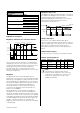
A Wall connection box
B Top section
C Cover plate
D Sensor head
E Contact pins
F Cable routing for bus line from underneath
G Cable routing for bus line from behind
H Terminal block for connecting the bus line and for lo-
cating the contact pins
Using ARGUS with alarm systems
Connections, displays and operating
elements
A
B
C
D
E
H
G
F
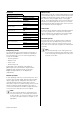
A Sensitivity controller
B Time controller
C Brightness controller
D Functional display, lights up each time movement is
detected
E Brightness sensor
F Programming area for magnet
G Programming LED
Explanation of the symbols used
When selecting a suitable installation site, you should
take a number of factors into account so that the move-
ment detector operates optimally.
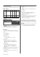
The following diagram shows the ranges of the ARGUS.
They are based on average temperature conditions at a
mounting height of 2.5 m. The range of a movement de-
tector can fluctuate considerably at variable tempera-
tures.
A Inner security zone with an angle of detection of
360° and a radius of approx. 4 m.
B Central security zone with an angle of detection of
220° and an area of detection of approx.
9mx18m.
C Outer security zone with an angle of detection of
220° and a detection area of approx. 16 m x 28 m.
Selecting the installation site
Correct
Not optimal
Incorrect
A
E
F
G
B
C
D
∞
0
2
4
6
8
10
2
4
6
8
10
12
12
14
14
0
4 2 4 6 8 10 12 14 16 m
B
0
0 2 4 6 8 10 12 14 16 m
2,5
m
4
0,8 m
2
C
A
D Select a mounting height between 2 m and 3 m. For
optimum monitoring, we recommend a height of 2.5
m on a solid and even base.
E Maintain a distance of at least 5 m from sources of
optical interference. Use the masking segments
provided if necessary.
In principle, you should not mount the luminaire under-
neath the ARGUS. The radiated heat from the luminaire
can influence the function of the movement detector and
lead to a permanent lighting circuit under certain condi-
tions.
F A minimum distance of 5 m should be maintained
between the luminaire and the movement detector.
If this distance cannot be achieved, you can use the
segments provided to "mask" the light source from
the area of detection.
If possible, install the movement detector sideways to the
direction of movement.
D
E
E
OK
OK
F
OK
OK
OK
½
CAUTION
The device can become damaged.
If installation is not carried out correctly, water can
penetrate the movement detector and damage it.
Always mount it with the spherical head pointing
downwards.
To avoid the connected load being switched on due to
environmental influences, the ARGUS should be in-
stalled so that it is protected against rain and direct sun-
light. A raindrop running over the lens, for example, can
activate the movement detector.
If you wish to attach several movement detectors, install
them so that the detection areas of the individual move-
ment detectors intersect each other.
1 Undo both screws and remove the wall connection
box from the device.
2 Mark drill holes on the mounting surface.
ARGUS installation
Bus
3 Feed in the bus line.
– To feed the bus line into the back of the device
from above, attach the spacers supplied to the
wall connection box.
– Feeding in the bus line from behind: slide the rub-
ber grommet A supplied over the stripped bus
line.
– Feeding in the bus line from below: cut the rubber
insert B supplied according to the cable thick-
ness. Insert the rubber insert into the wall connec-
tion box. Push the bus line through.
4 Mount the wall connection box.
Installing the ARGUS on the ceiling
In order to install the ARGUS on the ceiling, you must ro-
tate the sensor head. Change the direction of rotation
once you have reached the end stops.
1 Turn the sensor head upwards as far as it will go.
2 Turn the sensor head clockwise as far as it will go.
3 Align the sensor head.
B
A
1
2
3
1