
Operating instructions


V6325-561-00 03/08
½
CAUTION
If not installed correctly, the device can be
damaged by condensation.
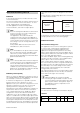
In the case of sloping ceilings, install the device
so that spherical head is pointing down and al-
ways at an angle of 15° - 90°. When the spherical
head points downwards, any water from conden-
sation could run down the device.
|
Type of protection IP 55 cannot be guaranteed if
the mounting bracket is not 15° - 90°.
Installing the ARGUS on corners and fixed pipes
You can attach the ARGUS to inner/outer corners or fixed
pipes using the Merten mounting bracket (art. no.
MTN5652..). You can feed the bus line to the device from
behind through the mounting bracket.
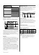
Connecting KNX
|
You can wire the bus line through the two termi-
nals (+) and (–) without encountering problems.
Installation of the top section of the ARGUS
1 Place the top section on the wall connection box
from the front.
2 Fasten the top section with the screws provided.
The electrical connection from the terminal box to the
contact pins is established automatically when the
screws are tightened.
3 Position the cover plate at the markings on the side,
and guide it upwards.
15° - 90°
KNX
+-
14 mm
1
23
The ARGUS operating elements are protected under a
cover plate. The arrow's position on the controllers
shows you the set values.
1 Push up the cover plate until you feel it hit the stop
(approx. 5 mm) and pull it off.
2 Guide a programming magnet (e.g. art. no.
MTN639190) over the programming area.
The programming LED lights up.
3 Load the physical address and application into the
device from the ETS.
The programming LED goes out when the application
has been loaded successfully. This device is ready for
operation.
Conducting a functional test
The brightness sensor must not be covered up.
1 Set the time controller to 1 second (left-hand stop).
Depending on the application program, you can either
set the time in the software or on the device.
2 Set the brightness controller to daytime operation
(infinity symbol/right-hand stop) or select the setting
"independent of brightness" in ETS.
3 Set the sensitivity controller to maximum (right-
hand stop).
The functional display lights up each time movement is
detected.
½
CAUTION
The device could become damaged.
The sensor head should only be rotated until it
reaches the stop and no further. To achieve an
angle "above" the stop, change the direction of
rotation.
1 Align the sensor head in the direction of the area
that is to be monitored.
2 From its edge step into the area of detection to see
whether the ARGUS switches the load and the func-
tional display as required.
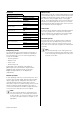
Putting ARGUS into operation
Setting ARGUS
9°
24°
12°12°
12° 12°
4°
29°
8,5°
8,5°
25°
25°
Setting the sensitivity
Here you can infinitely set the distance up to which AR-
GUS detects movements (any distance up to max.
16 m).
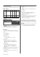
Setting the brightness threshold
Here you can infinitely set the ambient brightness level at
which the ARGUS detects movements and triggers a
switching procedure.
– Moon symbol (left stop) The ARGUS will only detect
movements during the hours of darkness (approx. 3
lux).
– Sun symbol: The ARGUS detects movements up to
approx. 1000 lux.
– Infinity symbol (right-hand stop): The ARGUS detects
movements regardless of the ambient brightness.
Setting the time
This makes it possible to set the overshoot time of the
connected loads. This is the time period from the last de-
tected movement until the load is switched off. Depend-
ing on the ETS application, the overshoot time is either
set in the ETS program (infinitely variable between
3 seconds and 152 hours) or directly on the ARGUS (six
steps of approx. 1 second to approx. 8 minutes).
|
Once the load has been switched on, the set
brightness threshold is ignored. Depending on
the settings in ETS, each registered movement
can reset the overshoot time. If the movement de-
tector no longer switches off, it is probably be-
cause it is continually detecting new movement
and is thus always extending the overshoot time.
Blocking out individual areas
Using the four segments supplied, you can block out un-
wanted zones and sources of interference from the area
of detection.
|
Ensure that the brightness sensor A is not cov-
ered, as the sensitivity to light is otherwise re-
duced.
3 LUX 1000 LUX
∞
A
12
If you have technical questions, please contact the Cus-
tomer Care Center in your country.
www.schneider-electric.com
This product must be installed, connected and used in
compliance with prevailing standards and/or installation
regulations. As standards, specifications and designs
develop from time to time, always ask for confirmation of
the information given in this publication.
Technical data
Nominal voltage: DC 24 V (+6 V / -4 V)
KNX connection: via terminal block
Power consumption: approx. 7 mA
Angle of detection: 220°
Range: max. 16 m
Number of levels: 7
Number of zones: 112 with 448 switching seg-
ments
Minimum
mounting height: 1.7 m
Recommended
mounting height: 2.5 m
Sensitivity: infinitely adjustable externally
Light sensor: infinitely adjustable externally,
from approx. 3 lux to approx.
1000 lux
Time: infinitely adjustable in the softwa-
re from 3 seconds to 152 hours
or adjustable externally in 6
steps from approx. 1 second to
approx. 8 minutes.
Programming: magnet-sensitive sensor for as-
signing the physical address.
Display elements: 1 red LED: Programming check,
1 red LED: Functional display
Possible settings for
the sensor head:
Wall mounting: 9° up, 24° down, 12° left/right,
±12° axial
Ceiling mounting: 4° up, 29° down, 25° left/right,
±8.5° axial
Type of protection: IP 55 at an angle of inclination
from 15° to 90°
Ambient temperature: -25 °C to +55 °C
EC guidelines: Low Voltage guideline 73/23/
EEC,
EMC guideline 89/336/EEC
Initialisation: Due to the limitation of the tele-
gram rate, a telegram cannot be
generated until at least 17 s after
the initialisation.
Schneider Electric Industries SAS
3