
Technical data

Chapter 5: ARGUS
5.1 ARGUS movement detector, surface-mounted
INSTABUS ARGUS 220 Connect
Art. no. 6315 ..
Version 03/04 2
Explanation of the symbols used
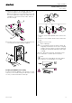
What you need to know about the installation site
¼
Danger due to electrical current!
All work on the device should only be carried
out by qualified electricians. Both the country-
specific regulations and the valid EIB guidelines
should be observed.
When selecting a suitable installation site, you should
take numerous standpoints into account so that the
movement detector operates at the optimum level.
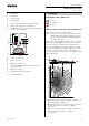
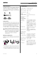
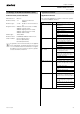
The following diagram shows the ranges of the AR-
GUS. They are based on average temperature conditi-
ons at a mounting height of 2.5 m. The range of a
movement detector can fluctuate considerably at vari-
able temperatures.
– A: Inner security zone with an angle of detection of
360° and a radius of approx. 4 m.
– B: Central security zone with an angle of detection
of 220° and an area of detection of approx.
9mx18m.
– C: Outer security zone with an angle of detection of
220° and an area of detection of approx.
16 m x 28 m.
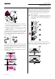
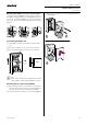
B Top section
C Cover plate
D Sensor head
E Contact pins
F Cable entry for bus line from underneath
G Cable entry for bus line from behind
H Terminal block for connecting the bus line and for
locating the contact pins
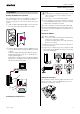
A Sensitivity controller
B Time controller
C Brightness controller
D Functional display, lights up each time move-
ment is detected
E Brightness sensor
F Programming area for magnet
G Programming LED
A
E
F
G
B
C
D
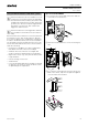
2. Installation
Correct
Not optimum
Incorrect
0
2
4
6
8
10
2
4
6
8
10
12
12
14
14
0
4 2 4 6 8 10 12 14 16m
C
B
A
0
0 2 4 6 8 10 12 14 16m
2,5m
m
4
0,8m
2