Operating and Installation Instructions Thrust actuator ARI-PREMIO-Plus Contents 1.0 General information on operating instructions...................................................................................... 3 2.0 Notes on possible dangers ...................................................................................................................... 3 2.1 Significance of symbols .................................................................................................................
5.0 Installation .............................................................................................................................................. 15 5.1 General installation data .................................................................................................................. 15 5.2 Manual operation ............................................................................................................................ 17 5.2.1 ARI-PREMIO 2.2 - 5 kN ........................
Operating and installation instructions Thrust actuator ARI-PREMIO-Plus 1.0 General information on operating instructions These operating instructions provide information on mounting, handling and maintaining the thrust actuators. Please contact the supplier or the manufacturer in case of problems which cannot be solved by reference to the operating instructions. They are binding on the transport, storage, installation, start-up, operation, maintenance and repair.
Operating and installation instructions Thrust actuator ARI-PREMIO-Plus 2.2 Explanatory notes on safety information In these Operating and Installation Instructions dangers, risks and items of safety information are highlighted to attract special attention. Information marked with the above symbol and “ATTENTION ! ” describe practices, a failure to comply with which can result in serious injury or danger of death for users or third parties or in material damage to the system or the environment.
Operating and installation instructions Thrust actuator ARI-PREMIO-Plus 4.0 Description 4.1 Field of application ARI-PREMIO linear thrust actuators are employed to actuate control or shut-off valves requiring a nominal linear stroke distance. The intelligent PREMIO-Plus thrust actuator is used whenever the actuator is controlled with an analogue signal (0 to 10 V / 4 to 20 mA) or a 3-point signal and feedback information about positions, operating states, faults, etc. has to be output.
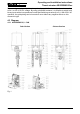
Operating and installation instructions Thrust actuator ARI-PREMIO-Plus Four unassigned relay outputs can be optionally supplied for alarm signals and connection to 24 V to 250 V DC/AC voltage. By using gold-plated contacts, it is possible to switch both binary inputs with a low operational current and switching currents up to 2 A. With 250 V AC operation, the gold plating can be burned off once without any negative effects on this connection type. 4.3 Diagram 4.3.
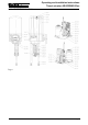
Operating and installation instructions Thrust actuator ARI-PREMIO-Plus 4.3.2 ARI-PREMIO 12 - 15 kN Fig.
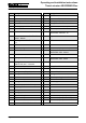
Operating and installation instructions Thrust actuator ARI-PREMIO-Plus 4.3.3 Parts list Pos. Designation Pos. Designation 50.1 Gearbox 50.36 Set collar 50.1.1 Gearbox cover plate 50.37 Grub screw DIN 913-M3x5 50.2 Cable gland 2 x M16x1.5 50.38 Guiding spindle 50.3 Blind disc 50.39 Hexagon nut DIN EN24034-M5 50.4 Sealing plug 1 x M16x1,5 50.40 Synchronous motor, complete 50.6 Hood 50.40.3 Motor capacitor 50.7 Hood seal 50.41 50.
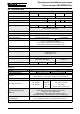
Operating and installation instructions Thrust actuator ARI-PREMIO-Plus 4.4 Technical data Type ARI-PREMIO Thrust force kN Stroke distance max. 5,0 mm Duty classification acc. to EN 60034-1/A11 Control speed 2,2 65 S3 80% DC/ max. 1200 c/h S3 50% DC / max. 1200 c/h 0.38 Motor voltage 1.0 230V - 50Hz / 60Hz W 15,0 50 mm/sec. Power consumption 12,0 24 0.38 0.79 1) 0.
Operating and installation instructions Thrust actuator ARI-PREMIO-Plus 4.5 Interface description 4.5.1 Control - Run commands Control Desciption - Technical data Required options OPEN-STOP-CLOSE (3-point) 2 Binary input - 12V to 240V AC - zero potential contacts - Modbus - Protocol: Modbus, Modbus-integer - Baud rate: 9600, 19200, 38400 - Device adress: 0 ... 255 - Max. number of participants: 32 - dTRON316 with RS422/485 card (dTRON options) Profibus-DP - Device adress: 0 ...
Operating and installation instructions Thrust actuator ARI-PREMIO-Plus 4.5.2 Feedback Position (analog) Position 2x - Intermediate positions - End positions Failure signal - Control signal failure - Position can not be achieved (motor / gear failure) - Blockage (actual) - Actuator is not initialized - Power failure Description Required option 4-20mA DC - Measuring resistance (Burden) max. 500 Ohm - Signal resolution 8 Bit - Analog output card PREMIO-Plus 0-10V DC - Measuring resistance (Burden) max.
Operating and installation instructions Thrust actuator ARI-PREMIO-Plus Warning signal - Manual operating device - Blocking (detected) - Position can not be achieved - Maintenance - Inside temperature exceeded - ED-management active - Leveling - too small travel during initialization Change over contact 30V AC/DC 2A - Relay card PREMIO-Plus Modbus - Protocol: Modbus, Modbusinteger - Baud rate: 9600, 19200, 38400 - Device adress: 0 ... 255 - Max.
Operating and installation instructions Thrust actuator ARI-PREMIO-Plus 4.5.3.3 Analog feedback signal For execution control in the Control / PLC following items have to be considered: - If the actuator is not initialized, 0V or 0mA is published. - When ANTI-Block ON, the actuator automatically tries to remove a blockage. For this, the plug is lifted up to 4 times with increasing travel. The lifting of the valve plug can also be seen on the feedback signal.
Page 14 ARI-PREMIO-Plus 2,2 - 5 kN Nominal stroke max. 30 mm Clearance required for removal of hood ARI-PREMIO-Plus 2,2 - 5 kN Nominal stroke > 30 mm - 50 mm Clearance required for removal of hood ARI-PREMIO-Plus 12 - 15 kN Nominal stroke max. 65 mm Clearance required for removal of hood X 236 256 271 286 L 633 653 668 683 h max. 30 mm max. 50 mm max. 65 mm max. 80 mm Operating and installation instructions Thrust actuator ARI-PREMIO-Plus 4.6 Dimensions Fig.
Operating and installation instructions Thrust actuator ARI-PREMIO-Plus 5.0 Installation ATTENTION ! - Work on electrical systems or equipment must only be carried out by qualified electricians or by trained individuals under the guidance and supervision of a qualified electrician in compliance with regional electrical safety requirements and regulations. - When connecting the thrust actuator the supply line must be disconnected from the mains (not live) during connection work.
Operating and installation instructions Thrust actuator ARI-PREMIO-Plus If installed outdoors, the thrust actuator must be provided with an additional cover to protect against: - rain, - direct insulation, - dust. Check thrust actuator for damage prior to fitting. Damaged parts must be replaced by original spares. The following must be provided: - Complete valve with crossbar and Operating Instructions.
Operating and installation instructions Thrust actuator ARI-PREMIO-Plus 5.2 Manual operation ATTENTION ! - The manual operating device always rotates during motor-driven operation (running indicator). Never activate the manual operating device while the motor is running.
Operating and installation instructions Thrust actuator ARI-PREMIO-Plus 5.3 Installation instructions for mounting to valves 5.3.1 Mounting for valve-lift up to 30 mm (yoke version) - Screw coupling (pos. 50.27) out of torsion safety feature (pos. 50.32) of thrust actuator (not illustrated). - Position valve cone approximately in mid lift position. Fig. 8-A: - Turn flat hexagon nut if not mounted yet on valve stem.
Operating and installation instructions Thrust actuator ARI-PREMIO-Plus Fig. 8-C: - Place thrust actuator (pos. 50) on valve. - Mount thrust actuator (pos. 50) on fitting with two T-head bolts (pos. 50.19), two washers (pos. 50.20), two spring washers (pos. 50.21), two hexagon nuts (pos. 50.22). Fig. 8-C turn Fig. 8-D/E - only 2,2-5 kN: Turn the manual operating device (pos. 50.130) with a wrench (a/f 17) and use it to move out the thrust actuator until the driving spindle (pos. 50.
Operating and installation instructions Thrust actuator ARI-PREMIO-Plus 5.3.2 Mounting for valve lift over 30 mm to 65 mm (column version) - Screw coupling (pos. 50.27) out of torsion safety feature (pos. 50.32) of thrust actuator (not illustrated). - Position valve cone approximately in mid lift position. Fig. 9-A: - Turn flat hexagon nut if not present on valve stem. ATTENTION ! X = 60/83mm --> Y = 102mm (+2mm) X = 98mm --> Y = 116mm (+2mm) Hexagon nut Valve stem Bild 9-A Hexagon nut Fig.
Operating and installation instructions Thrust actuator ARI-PREMIO-Plus Fig. 9-C: - Slip 2-ear clamp (pos. 50.26) onto a distance column (pos. 50.24) press on very lightly in such a way that one of the 2-ear clamps is situated above the torsion safety feature (pos. 50.32) and the other below. - Place thrust actuator (pos. 50) with distance columns onto valve and fix into position with two self-locking hexagon nuts (pos. 50.25). Bild 9-C turn Fig.
Operating and installation instructions Thrust actuator ARI-PREMIO-Plus 5.3.3 Setting dimensions for guiding stem ARI-PREMIO-Plus 2,2 -5 kN ARI-PREMIO-Plus 12 - 15 kN Yoke version Column version Column version 1. groove 2. groove 1. groove Fig. 10 -A Fig. 10-B Fig. 10-C ATTENTION ! for X = 60/83 mm --> 1. groove for X = 98 mm --> 2. groove Hexagon nut Valve stem Fig.
0040501004 5010 A-AB open B-AB open open 3-way valve with mixing plug closed Straight through valve Wire connections of the different valve types standard AB-A open AB-B open 3-way valve with diverting plug 230V/3A Binary outpu t (Out2) 230V/3A Binary output (Out1) Voltage 0(2)...10V Y out Analogue output card Relay Relay card Electronic temperature-controller dTRON 316 power supply Current 0(4)...
Fig. 12 Page 24 0040501004 5010 open closed Straight through valve AB-B open AB-A open B-AB open 3-way valve with diverting plug A-AB open 3-way valve with mixing plug Wire connections of the different valve types Standard Electronic temperature-controller dTRON 316 TTR Y out Analogue output card Relay Relay card Reversing contactor Heating resistor WS HZ Accessories Operating and installation instructions Thrust actuator ARI-PREMIO-Plus 5.4.
Operating and installation instructions Thrust actuator ARI-PREMIO-Plus 5.4.3 Connection Fig. 13: The complete electronics are delivered on the board support ATTENTION ! - Work on electrical systems or equipment must only be carried out by qualified electricians or by trained individuals under the guidance and supervision of a qualified electrician in compliance with regional electrical requirement and regulations.
Operating and installation instructions Thrust actuator ARI-PREMIO-Plus 5.5 Settings - Handling ATTENTION ! - The thrust actuator may only be operated for a short time without the hood for unavoidable setting operations to the electronics, the relay board and the electrical options. While these operations are in progress, the thrust actuator has hazardous, live, uninsulated parts exposed as well as moving and rotating parts.
Operating and installation instructions Thrust actuator ARI-PREMIO-Plus 5.5.
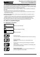
Operating and installation instructions Thrust actuator ARI-PREMIO-Plus Switch Meaning Description / explanation This 4-step slide switch takes priority over all other inputs and system states. In the position (up), the driving spindle is inserted into the gearbox until the corresponding travel switch is actuated. Local operation of the actuator In the "Stop" position, the motor is de-energised.
Operating and installation instructions Thrust actuator ARI-PREMIO-Plus Switch Meaning Description / explanation The Force switch specifies the direction in which the actuator is switched off by the thrust in the final position. - Switch up: Retracting spindle - Mid-position: Both directions - Switch down: Extending spindle The tight closing function is active in the set final position(s) to ensure that the valve is closed with the nominal actuator force.
Operating and installation instructions Thrust actuator ARI-PREMIO-Plus 5.6 Special functions 5.6.1 Economy – Wear reduction program With analogue control, actuator wear is reduced by the adaptive hysteresis band (refer to 7.4.1.2 General information about these Operating Instructions). With 3-point control, the control signals are converted with a time delay of one second. Several small control signals (<1 s) in the same direction are cumulated and executed with half an increment (0.
Operating and installation instructions Thrust actuator ARI-PREMIO-Plus 5.6.4 Temperature management The aim of the temperature management function is to prevent internal overheating.
Operating and installation instructions Thrust actuator ARI-PREMIO-Plus 5.6.7 Characteristics Valve characteristic + actuator characteristic = effective The slide switch for the characteristic sets characteristic three different actuator characteristics that define the relationship between the input signal and the valve position.
Operating and installation instructions Thrust actuator ARI-PREMIO-Plus 5.7 Options ATTENTION ! - The thrust actuator may only be operated for a short time without the hood for unavoidable setting operations to the electronics, the relay card and the electrical options. While these operations are in progress, the thrust actuator has hazardous, live, uninsulated parts exposed as well as moving and rotating parts.
Operating and installation instructions Thrust actuator ARI-PREMIO-Plus If a position is programmed for a switched Force switch, e.g. in a final position, the corresponding relay is only switched if this Force switch is actuated, regardless of the position. This can be the case if a blockage occurs, for instance. A blockage additionally results in a "Failure" signal because the desired position cannot be reached. 5.7.1.2 Technical data Type Switching capacity: UB Max.
Operating and installation instructions Thrust actuator ARI-PREMIO-Plus 5.7.1.5 Operation – Programming / clearing positions "Relay 1" LED (up) "Relay 1" button (up) "Relay 2" button (down) "Relay 2" LED (down) Fig. 20 Programming Procedure - Approach the spindle position. Relay 1 - Press "Relay 1 button (up)" until the corresponding LED blinks once. - From now on, relay 1 is switched to "active" when the current position is overtravelled in the UP direction. - Approach the spindle position.
Operating and installation instructions Thrust actuator ARI-PREMIO-Plus 5.7.2 Analogue output card – Yout Scope of supply: Pcs. Designation 1 Analogue output card 2 PT screws Fig. 21 5.7.2.1 Operating principle The actual position of the driving spindle can be signalled with the analogue output card. The connector for the output signal is already mounted on the motherboard. The feedback signal (4 to 20 mA, 0 to 10 V or inverted) corresponds to the switch configuration on the motherboard.
Operating and installation instructions Thrust actuator ARI-PREMIO-Plus 5.7.2.3 Installation procedure Fig. 22 Fig. 23 5.7.2.4 Electrical connection Fig.
Operating and installation instructions Thrust actuator ARI-PREMIO-Plus 5.7.3 Heating A heating resistor should be fitted as a means of protection against the formation of condensation water in cases involving widely varying ambient temperatures, high atmospheric humidity (outdoor use) and temperatures below the freezing point. The heating resistor is self-regulating so that a continuous supply of current merely needs to be connected up. 5.7.3.
Operating and installation instructions Thrust actuator ARI-PREMIO-Plus 5.7.4 Integrated temperature controller dTRON 316 The integrated temperature controller controls temperatures, which are measured by inputconnected temperature sensors, to a manual given setpoint by means of a three-step output connected with the actuator. 5.7.4.1 Installation of the dTRON 316 The dTRON 316 can be mounted in the ARI-PREMIO as a complete unit with a mounting kit.
Operating and installation instructions Thrust actuator ARI-PREMIO-Plus 6.0 Putting the actuator into operation ATTENTION ! All local safety instructions must be observed! Before putting a new plant into operation or restarting a plant after repair or modification, always make sure that: - The power supply, control signal and ambient temperature coincide with the technical data of the electronics.
Operating and installation instructions Thrust actuator ARI-PREMIO-Plus 6.2 Connecting the supply voltage The green status LED should light up when the supply voltage is connected to the N and L terminals. If not, the power should be disconnected again immediately in order to search for the fault (refer also to 11 Troubleshooting on page 28)! 6.
Operating and installation instructions Thrust actuator ARI-PREMIO-Plus 7.0 Care and maintenance NOTE ! The power supply cable must be disconnected from the mains (i.e. deenergised) prior to cleaning the electronics. Suitable precautions must be taken to prevent the mains voltage from being re-connected inadvertently. Non-observance can result in death, severe personal injury or substantial property damage. The thrust actuator requires very little maintenance.
Operating and installation instructions Thrust actuator ARI-PREMIO-Plus 9.0 Troubleshooting table ATTENTION ! - read point 10.0 and 11.0 prior to dismantling and repair work! - read point 6.
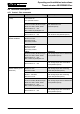
Operating and installation instructions Thrust actuator ARI-PREMIO-Plus Fault Actuator cannot be controlled with analogue control signal Possible Causes Actuator is set to 3-point operation or is currently controlled by a 3-point signal (indicated by lit LED above 3point connector) Actuator oscillates continuously about a point Xp setting on controller is too low Dead band setting on controller is too low Dirty slide Remedy By withdrawing the connector for the 3-point signal, you can determine whether
Operating and installation instructions Thrust actuator ARI-PREMIO-Plus NE 107 Colour NAMUR description PREMIO-Plus Out of specification Yellow Out of specification, unsafe due to environmental and process influences - CDF exceeded - Max.
Operating and installation instructions Thrust actuator ARI-PREMIO-Plus 9.2 LED encoding (from software version 2.1.7 and higher) No initialisation run Green Red Blockage Green Red Yin control signal failure Green Red ADV - outside the travel path Green Red Orange Position can not be achieved Green Red Orange Full travel too low Green Red Orange Orange Yellow Yellow Blue Yellow Blue 10.
Operating and installation instructions Thrust actuator ARI-PREMIO-Plus 11.0 Warranty / Guarantee The extent and period of warranty cover are specified in the "Standard Terms and Conditions of Albert Richter GmbH & Co. KG“ valid at the time of delivery or, by way of departure, in the contract of sale itself. We guarantee freedom of faults in compliance with state-of-the-art technology and the confirmed application.
Operating and installation instructions Thrust actuator ARI-PREMIO-Plus 12.0 EC declaration of conformity EC declaration of conformity as defined by Directive about electromagnetic compatibility 2004/108/EC and the EG-Low voltage directive 2006/95/EC Herewith we declare, ARI-Armaturen Albert Richter GmbH & Co.
Operating and installation instructions Thrust actuator ARI-PREMIO-Plus 0040501004 5010 Page 49
Operating and installation instructions Thrust actuator ARI-PREMIO-Plus Page 50 0040501004 5010